background image

Preparing for Installation

Voltage

Phases

Reference

High

3

Table 64, “High Voltage 3 Phase PDUs for Oracle Exadata Storage Expansion Rack,” on

page 292

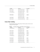
TABLE 61

Low Voltage 1 Phase PDUs for Oracle Exadata Storage Expansion Rack

High Voltage

One Phase

Comments

kVA Size

15 kVA

Marketing part number

N/A

Manufacturing part number

N/A

Phase

1 ph

Voltage

200 to 240 VAC

Amps per PDU

72 A (3 inputs x 24 A)

Outlets

42 C13

6 C19

Number of inputs

3 inputs

Input current

24 A max. per input

Data center receptacle

NEMA 30A/250 VAC 2-pole/3-wire L6-30P

Outlet groups per PDU

6

Usable PDU power cord length

2 m (6.6 feet)

PDU power cords are 4 m long (13 feet), but

sections are used for internal routing in the

rack.

TABLE 62

Low Voltage 3 Phase PDUs for Oracle Exadata Storage Expansion Rack

High Voltage

Three Phase

Comments

kVA Size

14.4 kVA

Marketing part number

N/A

Manufacturing part number

N/A

Phase

3 ph

Voltage

190 to 220 VAC

Amps per PDU

69 A (3 inputs x 23 A)

Outlets

42 C13

6 C19

Number of inputs

2 inputs x 60 A, 3 ph

Input current

40 A max. per phase

Data center receptacle

IEC 60309 60A 4-pin 250 VAC 3 ph IP 67

Outlet groups per PDU

6

Connecting Expansion Racks

291

Summary of Contents for SuperCluster T5-8

Page 1: ...Oracle SuperCluster T5 8 Owner s Guide Part No E40167 17 May 2016 ...

Page 2: ......

Page 3: ...rmation management applications It is not developed or intended for use in any inherently dangerous applications including applications that may create a risk of personal injury If you use this software or hardware in dangerous applications then you shall be responsible to take all appropriate fail safe backup redundancy and other measures to ensure its safe use Oracle Corporation and its affiliat...

Page 4: ...des informations Ce logiciel ou matériel n est pas conçu ni n est destiné à être utilisé dans des applications à risque notamment dans des applications pouvant causer un risque de dommages corporels Si vous utilisez ce logiciel ou ce matériel dans le cadre d applications dangereuses il est de votre responsabilité de prendre toutes les mesures de secours de sauvegarde de redondance et autres mesure...

Page 5: ...ding the Software Configurations 46 Understanding Domains 46 Understanding General Configuration Information 58 Understanding Half Rack Configurations 61 Understanding Full Rack Configurations 69 Understanding Clustering Software 84 Cluster Software for the Database Domain 85 Cluster Software for the Oracle Solaris Application Domains 85 Understanding the Network Requirements 86 Network Requiremen...

Page 6: ...Receiving Area Requirements 111 Access Route Guidelines 112 Unpacking Area 113 Preparing the Network 113 Network Connection Requirements 113 Network IP Address Requirements 114 Prepare DNS for the System 114 Installing the System 117 Installation Overview 117 Oracle Safety Information 118 Unpacking the System 119 Tools for Installation 119 Find the Unpacking Instructions 119 Unpack and Inspect the...

Page 7: ...Build Environment 150 Reboot to the Original Boot Environment 151 Remove Unwanted Boot Environments 151 Using Dynamic Intimate Shared Memory 151 DISM Restrictions 152 Disable DISM 152 Component Specific Service Procedures 153 Maintaining Exadata Storage Servers 153 Monitor Write through Caching Mode 154 Shut Down or Reboot an Exadata Storage Server 156 Drop an Exadata Storage Server 158 Tuning the...

Page 8: ...he System 205 Monitoring the System Using Auto Service Request 205 ASR Overview 205 ASR Resources 206 ASR Installation Overview 207 Configure SNMP Trap Destinations for Exadata Storage Servers 208 Configure ASR on the ZFS Storage Appliance 210 Configure ASR on SPARC T5 8 Servers Oracle ILOM 213 Configuring ASR on the SPARC T5 8 Servers Oracle Solaris 11 215 Approve and Verify ASR Asset Activation ...

Page 9: ...k 241 Understanding Internal Cabling 245 Connector Locations 245 Identifying InfiniBand Fabric Connections 253 IB Spine Switch 253 IB Leaf Switch No 1 253 IB Leaf Switch No 2 254 Ethernet Management Switch Connections 256 ZFS Storage Appliance Connections 258 Single Phase PDU Cabling 258 Three Phase PDU Cabling 259 Connecting Multiple Oracle SuperCluster T5 8 Systems 261 Multi Rack Cabling Overvie...

Page 10: ...Information for Oracle SuperCluster T5 8 315 InfiniBand Switch Information for the Oracle Exadata Storage Expansion Rack 316 Connecting an Oracle Exadata Storage Expansion Quarter Rack to Oracle SuperCluster T5 8 316 Connecting an Oracle Exadata Storage Expansion Half Rack or Oracle Exadata Storage Expansion Full Rack to Oracle SuperCluster T5 8 320 Two Rack Cabling 322 Three Rack Cabling 324 Four...

Page 11: ...Contents Index 353 11 ...

Page 12: ...12 Oracle SuperCluster T5 8 Owner s Guide May 2016 ...

Page 13: ...and authorized service providers Required knowledge Advanced experience in system installation and administration Product Documentation Library Documentation and resources for this product and related products are available on the system Access the documentation by using a browser to view this directory on the first compute server installed in SuperCluster T5 8 opt oracle node doc E40166_01 index ...

Page 14: ...14 Oracle SuperCluster T5 8 Owner s Guide May 2016 ...
Page 15: ... Cluster software This combination enables a high degree of isolation between concurrently deployed applications which have varied security reliability and performance requirements Oracle SuperCluster T5 8 enables customers to develop a single environment that can support end to end consolidation of their entire applications portfolio Oracle SuperCluster T5 8 provides an optimal solution for all d...

Page 16: ...ed by Oracle SuperCluster T5 8 offers significantly high bandwidth low latency hardware level reliability and security If you are using applications that follow Oracle s best practices for highly scalable fault tolerant systems you do not need to make any application architecture or design changes to benefit from Oracle SuperCluster T5 8 You can connect many Oracle SuperCluster T5 8 systems or a c...

Page 17: ...with Oracle SuperCluster T5 8 Customers may choose to the following Replace the Gigabit Ethernet switch at customer expense with an equivalent 1U 48 port Gigabit Ethernet switch that conforms to their internal data center network standards This replacement must be performed by the customer at their expense and labor after delivery of Oracle SuperCluster T5 8 If the customer chooses to make this ch...

Page 18: ... with the non standard modules If a server crashes and Oracle suspects the crash may have been caused by a non standard module then Oracle support may refer the customer to the vendor of the non standard module or ask that the issue be reproduced without the non standard module Modifying the Database Domain operating system other than by applying official patches and upgrades is not supported Infi...

Page 19: ...ta Storage Servers and the ZFS storage appliance Sun ZFS Storage 7320 appliance or Oracle ZFS Storage ZS3 ES storage appliance as well as required InfiniBand and Ethernet networking components This section contains the following topics Full Rack Components on page 20 Half Rack Components on page 22 Understanding the System 19 ...

Page 20: ...Identifying Hardware Components Full Rack Components FIGURE 1 Oracle SuperCluster T5 8 Full Rack Layout Front View 20 Oracle SuperCluster T5 8 Owner s Guide May 2016 ...

Page 21: ...n expand the amount of disk storage for your system using the Oracle Exadata Storage Expansion Rack See Oracle Exadata Storage Expansion Rack Components on page 287 for more information You can connect up to eight Oracle SuperCluster T5 8 systems together or a combination of Oracle SuperCluster T5 8 systems and Oracle Exadata or Exalogic machines on the same InfiniBand fabric without the need for ...

Page 22: ...Identifying Hardware Components Half Rack Components FIGURE 2 Oracle SuperCluster T5 8 Half Rack Layout Front View 22 Oracle SuperCluster T5 8 Owner s Guide May 2016 ...

Page 23: ...iBand fabric without the need for any external switches See Connecting Multiple Oracle SuperCluster T5 8 Systems on page 261 for more information Understanding the Hardware Components and Connections These topics describe how the hardware components and connections are configured to provide full redundancy for high performance or high availability in Oracle SuperCluster T5 8 as well as connections...

Page 24: ...ains four processor modules There are two sockets or PCIe root complex pairs on each processor module where 16 cores are associated with each socket for a total of eight sockets or PCIe root complex pairs 128 cores for each SPARC T5 8 server For the Half Rack version of Oracle SuperCluster T5 8 each SPARC T5 8 server contains two processor modules There are two sockets or PCIe root complex pairs o...

Page 25: ...e Sun Disk Shelf can continue to operate normally if one of those power supplies fails Disk drives Each ZFS storage controller contains two mirrored boot drives so the controller can still boot up and operate normally if one boot drive fails The Sun Disk Shelf contains 20 hard disk drives that are used for storage in Oracle SuperCluster T5 8 and 4 solid state drives that are used as write optimize...

Page 26: ...ents within Oracle SuperCluster T5 8 Understanding the SPARC T5 8 Server Physical Connections on page 26 Understanding the Exadata Storage Server Physical Connections on page 36 Understanding the ZFS Storage Appliance Physical Connections on page 39 Power Distribution Units Physical Connections on page 45 Understanding the SPARC T5 8 Server Physical Connections These topics provide information on ...

Page 27: ...ssor modules and the Half Rack has two processor modules See SPARC T5 8 Servers on page 24 for more information Each SPARC T5 8 server has sixteen PCIe slots Full Rack All 16 PCIe slots are accessible and all 16 PCIe slots are occupied with either InfiniBand HCAs or 10 GbE NICs Half Rack All 16 PCIe slots are accessible but only eight of the 16 PCIe slots are occupied with either InfiniBand HCAs o...

Page 28: ...Understanding the Hardware Components and Connections FIGURE 3 Topology for the Full Rack Version of Oracle SuperCluster T5 8 28 Oracle SuperCluster T5 8 Owner s Guide May 2016 ...

Page 29: ...lf Rack Version of Oracle SuperCluster T5 8 Card Locations SPARC T5 8 Servers The following figures show the cards that will be used for the physical connections for the SPARC T5 8 server in the Full Rack and Half Rack versions of Oracle SuperCluster T5 8 Understanding the System 29 ...

Page 30: ... See Using an Optional Fibre Channel PCIe Card on page 139 for more information FIGURE 5 Card Locations Full Rack Figure Legend 1 Dual port 10 GbE network interface cards for connection to the 10 GbE client access network see 10 GbE Client Access Network Physical Connections SPARC T5 8 Servers on page 35 2 Dual port InfiniBand host channel adapters for connection to the InfiniBand network see Infi...

Page 31: ... Physical Connections SPARC T5 8 Servers on page 35 2 Dual port InfiniBand host channel adapters for connection to the InfiniBand network see InfiniBand Private Network Physical Connections SPARC T5 8 Servers on page 32 NET MGT and NET0 3 Port Locations SPARC T5 8 Servers The following figure shows the NET MGT and NET0 3 ports that will be used for the physical connections for the SPARC T5 8 serve...

Page 32: ...e Network Physical Connections SPARC T5 8 Servers Each SPARC T5 8 server contains several dual ported Sun QDR InfiniBand PCIe Low Profile host channel adapters HCAs The number of InfiniBand HCAs and their locations in the SPARC T5 8 servers varies depending on the configuration of Oracle SuperCluster T5 8 Full Rack Eight InfiniBand HCAs installed in these PCIe slots PCIe slot 3 PCIe slot 4 PCIe sl...

Page 33: ...ports 1 and 2 connect to a different leaf switch to provide redundancy between the SPARC T5 8 servers and the leaf switches The following figures show how redundancy is achieved with the InfiniBand connections between the SPARC T5 8 servers and the leaf switches in the Full Rack and Half Rack configurations FIGURE 8 InfiniBand Connections for SPARC T5 8 Servers Full Rack Understanding the System 3...

Page 34: ...mains are created for each SPARC T5 8 server the InfiniBand private network will be configured differently depending on the type of domain created on the SPARC T5 8 servers The number of IP addresses needed for the InfiniBand network will also vary depending on the type of domains created on each SPARC T5 8 server For more information see Understanding the Software Configurations on page 46 34 Ora...

Page 35: ... 8 server NET0 NET3 ports However the way the 1 GbE host management connections are used differs from the physical connections due to logical domains For more information see Understanding the Software Configurations on page 46 See NET MGT and NET0 3 Port Locations SPARC T5 8 Servers on page 31 for more information on the location of the 1 GbE host management ports 10 GbE Client Access Network Phy...

Page 36: ...Exadata Storage Server contains three sets of physical connections InfiniBand Private Network Physical Connections Exadata Storage Servers on page 36 Oracle ILOM Management Network Physical Connections Exadata Storage Servers on page 38 1 GbE Host Management Network Physical Connections Exadata Storage Servers on page 39 InfiniBand Private Network Physical Connections Exadata Storage Servers Each ...

Page 37: ...edundancy is achieved with the InfiniBand connections between the Exadata Storage Servers and the leaf switches in the Full Rack and Half Rack configurations FIGURE 10 InfiniBand Connections for Exadata Storage Servers Full Rack Understanding the System 37 ...

Page 38: ...k Physical Connections Exadata Storage Servers Each Exadata Storage Server connects to the Oracle ILOM management network through a single Oracle ILOM network port NET MGT port at the rear of each Exadata Storage Server One IP address is required for Oracle ILOM management for each Exadata Storage Server 38 Oracle SuperCluster T5 8 Owner s Guide May 2016 ...

Page 39: ... on page 42 Cluster Physical Connections ZFS Storage Appliance on page 44 InfiniBand Private Network Physical Connections ZFS Storage Appliance The ZFS storage appliance connects to the InfiniBand private network through one of the two ZFS storage controllers The ZFS storage controller contains one Sun Dual Port 40Gb InfiniBand QDR HCA The two ports in each InfiniBand HCA are bonded together to in...

Page 40: ...Understanding the Hardware Components and Connections FIGURE 12 InfiniBand Connections for ZFS Storage Controllers Full Rack 40 Oracle SuperCluster T5 8 Owner s Guide May 2016 ...

Page 41: ...Appliance The ZFS storage appliance connects to the Oracle ILOM management network through the two ZFS storage controllers Each storage controller connects to the Oracle ILOM management network through the NET0 port at the rear of each storage controller using sideband management One IP address is required for Oracle ILOM management for each storage controller Understanding the System 41 ...

Page 42: ...One IP address is required for 1 GbE host management for each storage controller SAS Physical Connections ZFS Storage Appliance Each ZFS storage controller is populated with a dual port SAS 2 HBA card The Sun Disk Shelf also has two SIM Link In and two SIM Link Out ports The two storage controllers connect to the Sun Disk Shelf in the following manner Storage controller 1 Both ports from the SAS 2...

Page 43: ...he Hardware Components and Connections FIGURE 14 SAS Connections for the Sun ZFS Storage 7320 Storage Appliance Figure Legend 1 Storage controller 1 2 Storage controller 2 3 Sun Disk Shelf Understanding the System 43 ...

Page 44: ... ZFS Storage Appliance Each ZFS storage controller contains a single cluster card The cluster cards in the storage controllers are cabled together as shown in the following figure This allows a heartbeat signal to pass between the storage controllers to determine if both storage controllers are up and running 44 Oracle SuperCluster T5 8 Owner s Guide May 2016 ...

Page 45: ...ge controller has two AC power connectors One AC power connector connects to one power distribution unit and the other AC power connector connects to the other power distribution unit Sun Disk Shelf The Sun Disk Shelf has two AC power connectors One AC power connector connects to one power distribution unit and the other AC power connector connects to the other power distribution unit Sun Datacent...

Page 46: ...e to four domains Full Rack version of Oracle SuperCluster T5 8 One to eight domains These topics describe the domain types Dedicated Domains on page 46 Understanding SR IOV Domain Types on page 48 Dedicated Domains The following SuperCluster specific domain types have always been available Application Domain running Oracle Solaris 10 Application Domain running Oracle Solaris 11 Database Domain Th...

Page 47: ...network go through the physical ports on each 10GbE NIC and connections to the IB network go through the physical ports on each IB HCA as shown in the following graphic With dedicated domains the domain configuration for a SuperCluster the number of domains and the SuperCluster specific types assigned to each are set at the time of the initial installation and can only be changed by an Oracle repr...

Page 48: ...re set at the time of the initial installation and can only be changed by an Oracle representative Type of domain Root Domain Application Domain running Oracle Solaris 10 dedicated domain Application Domain running Oracle Solaris 11 dedicated domain Database Domain dedicated domain Number of Root Domains and dedicated domains on the server A domain can only be a Root Domain if it has either one or...

Page 49: ... memory is always reserved for each Root Domain depending on which domain is being used as a Root Domain in the domain configuration and the number of IB HCAs and 10GbE NICs that are associated with that Root Domain The last domain in a domain configuration Two cores and 32 GB of memory reserved for a Root Domain with one IB HCA and 10GbE NIC Four cores and 64 GB of memory reserved for a Root Doma...

Page 50: ...ervers have Root Domains there would be two sets of CPU and memory repositories where each compute server would have its own CPU and memory repositories with parked resources For example assume you have four domains on your compute server with three of the four domains as Root Domains as shown in the previous graphic Assume each domain has the following IB HCAs and 10GbE NICs and the following CPU...

Page 51: ...s With Root Domains connections to the 10GbE client access network go through the physical ports on each 10GbE NIC and connections to the IB network go through the physical ports on each IB HCA just as they did with dedicated domains However cards used with Root Domains must also be SR IOV compliant SR IOV compliant cards enable VFs to be created on each card where the virtualization occurs in the...

Page 52: ...Applications and zones are supported only in I O Domains not in Root Domains You can create multiple I O Domains using the I O Domain Creation tool As part of the domain creation process you also associate one of the following SuperCluster specific domain types to each I O Domain Application Domain running Oracle Solaris 11 Database Domain Note that only Database Domains that are dedicated domains...

Page 53: ... resources that you want to assign to each I O Domain and the total amount of CPU core and memory resources available in the CPU and memory repositories Similarly the IB VFs and 10GbE VFs owned by the I O Domains come from the IB VF and 10GbE VF repositories the IB VFs and 10GbE VFs released from Root Domains on the system as shown in the following graphic Understanding the System 53 ...

Page 54: ... and size of the I O Domains that you can create depends on several factors including the amount of CPU core and memory resources that are available in the CPU and memory repositories and the amount of CPU core and memory resources that you want to assign to each I O Domain However while it is useful to know the total amount of resources are that are parked in the repositories it does not necessar...

Page 55: ...e to several factors such as reaching the limit of total CPU core and memory resources in the CPU and memory repositories reaching the limit of resources available specifically to you as a user or reaching the limit on the number of I O Domains allowable for this system Note The following examples describe how resources might be divided up between domains using percentages to make the conceptual i...

Page 56: ... you could request that each dedicated domain have 30 of the CPU core and memory resources for a total of 90 of the CPU cores and memory resources allocated to the three dedicated domains and the remaining 10 allocated to the single Root Domain Having this configuration would mean that only 10 of the CPU core and memory resources are available for I O Domains to pull from the CPU and memory reposi...

Page 57: ...unless you have the Oracle installer come back out to your site to reconfigure your system See Configuring CPU and Memory Resources osc setcoremem on page 170 for more information Assume you have a mixture of dedicated domains and Root Domains as mentioned earlier where each dedicated domain has 30 of the CPU core and memory resources total of 90 resources allocated to dedicated domains and the re...

Page 58: ... to connect to the private InfiniBand network See PCIe Slots SPARC T5 8 Servers on page 27 and Card Locations SPARC T5 8 Servers on page 29 for more information Optional Fibre Channel PCIe cards are also available to facilitate migration of data from legacy storage subsystems to the Exadata Storage Servers integrated with Oracle SuperCluster T5 8 for Database Domains or to access SAN based storage...

Page 59: ... type of configuration that is set up on the SPARC T5 8 server 10 GbE Client Access Network Overview This required 10 GbE network connects the SPARC T5 8 servers to your existing client network and is used for client access to the servers 10 GbE NICs installed in the PCIe slots are used for connection to this network The number of 10 GbE NICs and the PCIe slots that they are installed in varies de...

Page 60: ...Database Domain the following InfiniBand private networks are used Storage private network One InfiniBand private network for the Database Domains to communicate with each other and with the Application Domains running Oracle Solaris 10 and with the ZFS storage appliance Exadata private network One InfiniBand private network for the Oracle Database 11g Real Application Clusters Oracle RAC intercon...

Page 61: ...the ZFS storage appliance Oracle Solaris Cluster private network Two InfiniBand private networks for the optional Oracle Solaris Cluster interconnects The two ports on each InfiniBand HCA will connect to different Sun Datacenter InfiniBand Switch 36 leaf switches to provide redundancy between the SPARC T5 8 servers and the leaf switches For more information on the physical connections for the SPAR...

Page 62: ...onfigurations for the Half Rack It also provides information on the PCIe slots and the InfiniBand IB HCAs or 10 GbE NICs installed in each PCIe slot and which logical domain those cards would be mapped to for the Half Rack FIGURE 16 Logical Domain Configurations and PCIe Slot Mapping Half Rack Related Information Understanding Large Domains Half Rack on page 63 Understanding Medium Domains Half Ra...

Page 63: ...change this default allocation after the initial installation of your system if you want to have some CPU or memory resources parked unused See Configuring CPU and Memory Resources osc setcoremem on page 170 for more information Management Network Two out of the four 1 GbE host management ports are part of one IPMP group for this domain NET0 NET3 10 GbE Client Access Network All four PCI root comp...

Page 64: ...ast CPU in the domain So for a Large Domain in a Half Rack these connections would be through P1 on the InfiniBand HCA installed in slot 3 active and P0 on the InfiniBand HCA installed in slot 16 standby Exadata private network Connections through P0 active and P1 standby on all InfiniBand HCAs associated with the domain So for a Large Domain in a Half Rack connections will be made through all fou...

Page 65: ...ne socket for the first Medium Domain three sockets for the second Medium Domain Three sockets for the first Medium Domain one socket for the second Medium Domain Four cores for the first Medium Domain the remaining cores for the second Medium Domain first Medium Domain must be either a Database Domain or an Application Domain running Oracle Solaris 11 in this case Config H3 1 One Medium Domain an...

Page 66: ...n the IPMP group even if one of the two 10 GbE NICs fail Note You can also connect just one port in each IPMP group to the 10 GbE network rather than both ports if you are limited in the number of 10 GbE connections that you can make to your 10 GbE network However you will not have the redundancy and increased bandwidth in this case InfiniBand Network The connections to the InfiniBand network vary...

Page 67: ...main in a Half Rack these connections would be through P0 on the InfiniBand HCA installed in slot 3 active and P1 on the InfiniBand HCA installed in slot 11 standby Understanding Small Domains Half Rack These topics provide information on the Small Domain configuration for the Half Rack Percentage of CPU and Memory Resource Allocation on page 67 Management Network on page 68 10 GbE Client Access N...

Page 68: ...ch 10 GbE NIC would be part of one IPMP group Both ports from each dual ported 10 GbE NIC is connected to the 10 GbE network for the Small Domains The following 10 GbE NICs and ports are used for connection to the client access network for the Small Domains depending on the CPU that the Small Domain is associated with CPU0 PCIe slot 1 port 0 active PCIe slot 1 port 1 standby CPU1 PCIe slot 9 port ...

Page 69: ...r a Small Domain that is associated with CPU0 these connections would be through the InfiniBand HCA installed in slot 3 through ports P0 active and P1 standby on that InfiniBand HCA Application Domain Storage private network Connections through P1 active and P0 standby on the InfiniBand HCA associated with the CPU associated with each Small Domain For example for a Small Domain that is associated ...

Page 70: ...page 72 Understanding Large Domains Full Rack on page 74 Understanding Medium Domains Full Rack on page 77 Understanding Small Domains Full Rack on page 80 Logical Domain Configurations and PCIe Slot Mapping Full Rack The following figure provides information on the available configurations for the Full Rack It also provides information on the PCIe slots and the InfiniBand IB HCAs or 10 GbE NICs i...

Page 71: ...ons and PCIe Slot Mapping Full Rack Related Information Understanding Giant Domains Full Rack on page 72 Understanding Large Domains Full Rack on page 74 Understanding Medium Domains Full Rack on page 77 Understanding Small Domains Full Rack on page 80 Understanding the System 71 ...

Page 72: ...urces parked unused See Configuring CPU and Memory Resources osc setcoremem on page 170 for more information Management Network Two out of the four 1 GbE host management ports are part of one IPMP group for this domain NET0 NET3 10 GbE Client Access Network All eight PCI root complex pairs and therefore eight 10 GbE NICs are associated with the logical domain on the server in this configuration Ho...

Page 73: ...standby Exadata private network Connections through P0 active and P1 standby on all InfiniBand HCAs associated with the domain So for a Giant Domain in a Full Rack connections will be made through all eight InfiniBand HCAs with P0 on each as the active connection and P1 on each as the standby connection Application Domain Storage private network Connections through P1 active on the InfiniBand HCA ...

Page 74: ...or the second Large Domain Config F3 1 One Large Domain and two Medium Domains The following options are available for CPU and memory resource allocation Four sockets for the Large Domain two sockets apiece for the two Medium Domains Two sockets for the Large Domain four sockets for the first Medium Domain two sockets for the second Medium Domain Two sockets for the Large Domain and the first Medi...

Page 75: ...in Two sockets for the Large Domain and the for the first Small Domain one socket apiece for the second and third Small Domains two sockets for the fourth Small Domain Management Network Two 1 GbE host management ports are part of one IPMP group for each Large Domain Following are the 1 GbE host management ports associated with each Large Domain depending on how many domains are on the SPARC T5 8 ...

Page 76: ...ed in slot 12 standby Exadata private network Connections through P0 active and P1 standby on all InfiniBand HCAs associated with the domain So for a Large Domain in a Full Rack connections will be made through the four InfiniBand HCAs associated with the domain with P0 on each as the active connection and P1 on each as the standby connection Application Domain Storage private network Connections ...

Page 77: ...e Large Domain one socket apiece for the two Medium Domains Five sockets for the Large Domain two sockets for the first Medium Domain one socket for the second Medium Domain Five sockets for the Large Domain one socket for the first Medium Domain two sockets for the second Medium Domain Config F4 1 Four Medium Domains The following options are available for CPU and memory resource allocation Two s...

Page 78: ...socket for the first Small Domain two sockets for the second Small Domain one socket for the third Medium Domain Two sockets for the first Medium Domain one socket for the second Medium Domain two sockets for the first Small Domain one socket for the second Small Domain two sockets for the third Medium Domain Config F6 1 Two Medium Domains four Small Domains The following options are available for...

Page 79: ...andby CPU2 CPU3 PCIe slot 2 port 0 active PCIe slot 10 port 1 standby CPU4 CPU5 PCIe slot 5 port 0 active PCIe slot 13 port 1 standby CPU6 CPU7 PCIe slot 6 port 0 active PCIe slot 14 port 1 standby A single data address is used to access these two physical ports That data address allows traffic to continue flowing to the ports in the IPMP group even if the connection to one of the two ports on the...

Page 80: ...P0 on the InfiniBand HCA installed in slot 11 standby Oracle Solaris Cluster private network Connections through P0 active on the InfiniBand HCA associated with the first CPU in the domain and P1 standby on the InfiniBand HCA associated with the second CPU in the domain For example for first Medium Domain in a Full Rack these connections would be through P0 on the InfiniBand HCA installed in slot ...

Page 81: ...esource allocation Two sockets apiece for the first and second Medium Domains one socket apiece for the first and second Small Domains two sockets for the third Medium Domain One socket for the first Medium Domain two sockets for the second Medium Domain one socket for the first Small Domain two sockets apiece for the second Small Domain and the third Medium Domain Two sockets apiece for the first...

Page 82: ...fig F8 1 Eight Small Domains One socket for each Small Domain Management Network The number and type of 1 GbE host management ports that are assigned to each Small Domain varies depending on the CPU that the Small Domain is associated with CPU0 NET0 1 CPU1 NET1 NET3 through virtual network devices CPU2 NET0 NET2 through virtual network devices CPU3 NET1 NET3 through virtual network devices CPU4 NE...

Page 83: ...14 port 0 active PCIe slot 14 port 1 standby A single data address is used to access these two physical ports That data address allows traffic to continue flowing to the ports in the IPMP group even if the connection to one of the two ports on the 10 GbE NIC fails Note You can also connect just one port in each IPMP group to the 10 GbE network rather than both ports if you are limited in the numbe...

Page 84: ...olaris Cluster private network Connections through P0 active and P1 standby on the InfiniBand HCA associated with the CPU associated with each Small Domain For example for a Small Domain that is associated with CPU0 these connections would be through the InfiniBand HCA installed in slot 3 through ports P0 active and P1 standby on that InfiniBand HCA Understanding Clustering Software Clustering sof...

Page 85: ...one to many relationship between the database and instances In Oracle RAC environments the cluster database instances access one database The combined processing power of the multiple servers can provide greater throughput and scalability than is available from a single server Oracle RAC is the Oracle Database option that provides a single system image for multiple servers to access one Oracle dat...

Page 86: ... Oracle Integrated Lights Out Manager Oracle ILOM remote management Either 4 Half Rack or 8 Full Rack dual ported Sun QDR InfiniBand PCIe Low Profile host channel adapters HCAs for connection to the InfiniBand private network Either 4 Half Rack or 8 Full Rack dual ported Sun Dual 10 GbE SFP PCIe 2 0 Low Profile network interface cards NICs for connection to the 10 GbE client access network Note Th...

Page 87: ...be required for the switch to operate properly in your environment and is beyond the scope of the installation service If additional configuration is needed then your network administrator must perform the necessary configuration steps during installation of Oracle SuperCluster T5 8 To deploy Oracle SuperCluster T5 8 ensure that you meet the minimum network requirements There are three networks fo...

Page 88: ...agement interfaces on the SPARC T5 8 servers should not be used for client or application network traffic Cabling or configuration changes to these interfaces is not permitted Client access network This required 10 GbE network connects the SPARC T5 8 servers to your existing client network and is used for client access to the servers Database applications access the database through this network u...

Page 89: ... T5 8 installation TABLE 1 New Network Connections Required for Installation Connection Type Number of connections Comments Management network 1 for Ethernet switch Connect to the existing management network Client access network Typically 2 per logical domain Connect to the client access network You will not have redundancy through IPMP if there is only one connection per logical domain Understan...

Page 90: ...controllers If you are connecting Oracle SuperCluster T5 8 to another Oracle SuperCluster T5 8 or to an Oracle Exadata or Exalogic machine on the same InfiniBand fabric the InfiniBand interface enables communication between the SPARC T5 8 servers and storage server heads in one Oracle SuperCluster T5 8 and the other Oracle SuperCluster T5 8 or Oracle Exadata or Exalogic machine 10 GbE IP addresses...

Page 91: ...168 1 107 cell07 192 168 1 7 38 37 Exadata Storage Server 6 Full Rack only ssces6 sp 192 168 1 106 cell06 192 168 1 6 36 35 Exadata Storage Server 5 Full Rack only ssces5 sp 192 168 1 105 cell05 192 168 1 5 34 ZFS Storage Controller 2 sscsn2 sp 192 168 1 116 sscsn2 m1 192 168 1 16 33 ZFS Storage Controller 1 sscsn1 sp 192 168 1 115 sscsn1 m1 192 168 1 15 32 Sun Datacenter InfiniBand Switch 36 Leaf...

Page 92: ...1 101 cell01 192 168 1 1 1 Sun Datacenter InfiniBand Switch 36 Spine sscnm1 m1 192 168 1 201 N A N A Default Host Names and IP Addresses for the InfiniBand and 10 GbE Client Access Networks TABLE 3 Default Host Names and IP Addresses for the InfiniBand and 10 GbE Client Access Networks Information Assigned at Manufacturing Unit Number Rack Component Front View InfiniBand Host Names InfiniBand IP A...

Page 93: ... N A N A 26 Sun Datacenter InfiniBand Switch 36 Leaf 1 N A N A N A N A 25 ssccn2 ib8 192 168 10 80 ssccn2 tg16 ssccn2 tg15 192 168 40 32 192 168 40 31 24 ssccn2 ib7 192 168 10 70 ssccn2 tg14 ssccn2 tg13 192 168 40 30 192 168 40 29 23 ssccn2 ib6 192 168 10 60 ssccn2 tg12 ssccn2 tg11 192 168 40 28 192 168 40 27 22 ssccn2 ib5 192 168 10 50 ssccn2 tg10 ssccn2 tg9 192 168 40 26 192 168 40 25 21 ssccn2 ...

Page 94: ...92 168 40 9 13 ssccn1 ib4 192 168 10 39 ssccn1 tg8 ssccn1 tg7 192 168 40 8 192 168 40 7 12 ssccn1 ib3 192 168 10 29 ssccn1 tg6 ssccn1 tg5 192 168 40 6 192 168 40 5 11 ssccn1 ib2 192 168 10 19 ssccn1 tg4 ssccn1 tg3 192 168 40 4 192 168 40 3 10 ssccn1 ib1 192 168 10 9 ssccn1 tg2 ssccn1 tg1 192 168 40 2 192 168 40 1 9 8 Exadata Storage Server 4 ssces4 stor 192 168 10 104 N A N A 7 6 Exadata Storage S...

Page 95: ...r the new rack Do not install the rack in a location that is exposed to Direct sunlight Excessive dust Corrosive gases Air with high salt concentrations Frequent vibrations Sources of strong radio frequency interference Static electricity Use power outlets that provide proper grounding A qualified electrical engineer must perform any grounding work Each grounding wire for the rack must be used onl...

Page 96: ... physical specifications and space requirements Parameter Metric English Height 1998 mm 78 66 in Width with side panels 600 mm 23 62 in Depth with doors 1200 mm 47 24 in Depth without doors 1112 mm 43 78 in Minimum ceiling height 2300 mm 90 in Minimum space between top of cabinet and ceiling 914 mm 36 in Weight full rack 869 kg 1 916 lbs Weight half rack 706 kg 1 556 lbs Related Information Instal...

Page 97: ...out Dimensions If you plan to route cables down through the bottom of the rack cut a rectangular hole in the floor tile Locate the hole below the rear portion of the rack between the two rear casters and behind the rear inner rails The suggested hole width is 280 mm 11 inches If you want a separate grounding cable see Install a Ground Cable Optional on page 124 Caution Do not create a hole where t...

Page 98: ...dge of the rack is 113 mm 4 45 inches 4 Distance between the centers of the front and rear mounting hole slots is 1120 mm 44 1 inches 5 Depth of cable routing floor cutout is 330 mm 13 inches 6 Distance between the floor cutout and the edge of the rack is 160 mm 6 3 inches 7 Width of floor cutout is 280 mm 11 inches Related Information Perforated Floor Tiles on page 110 Physical Specifications on ...

Page 99: ...ated power for the rack For rated power specifications see PDU Power Requirements on page 101 TABLE 4 SuperCluster T5 8 Condition Full Rack Half Rack Maximum Typical 15 97 kVA 15 17 kW 13 31 kVA 12 64 kW 9 09 kVA 8 6 kW 7 5 kVA 7 13 kW TABLE 5 Exadata X5 2 Expansion Rack Product Condition kW kVA Extreme Flash quarter rack Maximum Typical 3 6 2 5 3 7 2 6 High capacity quarter rack Maximum Typical 3...

Page 100: ...er distribution system an uninterruptible power supply UPS power conditioning equipment and lightning arresters Related Information Power Consumption on page 99 Grounding Requirements on page 100 PDU Power Requirements on page 101 Grounding Requirements Always connect the cords to grounded power outlets Computer equipment requires electrical circuits to be grounded to the Earth Because different g...

Page 101: ...n page 102 High 1 Table 9 High Voltage 1 Phase PDUs on page 103 High 3 Table 10 High Voltage 3 Phase PDUs on page 103 TABLE 7 Low Voltage 2 Phase PDUs Low Voltage Dual Phase 2W GND Comments kVA Size 22 kVA Marketing part number 7100873 Manufacturing part number 7018123 Phase 2 No Grounded Neutral provided in input cords Voltage input rating 3x 2Ph 2W ground 208 Vac 50 60 Hz max 36 8A per phase Can...

Page 102: ... 597 1162 01 Phase 3 No Grounded Neutral provided in input cords Voltage input rating 2x 3Ph 3W ground 208 Vac 50 60 Hz max 34 6A per phase Can be connected to Ph Ph input sources in range of 190V 220V AC nominal Amps per PDU 120A 3 x 20A Outlets 42 C13 6 C19 Number of inputs 2 inputs x 60A plug 3 ph 3W GND 2 inputs plugs per PDU or 4 total inputs plugs for system Input current 34 6 A max per phas...

Page 103: ...eceptacle IEC 309 2P3W IP44 Outlet groups per PDU 6 Usable PDU power cord length 2 m 6 6 feet PDU power cords are 4 m long 13 feet but sections are used for internal routing in the rack Summary Number of PDUs in Oracle SuperCluster T5 8 2 Number of circuits per PDU 3 32A 1 phase 230V Total number of circuits required 6 32A 1 phase 230V 2 per PDU Total number of data center receptacles required 6 x...

Page 104: ...ter receptacles required 4 x IEC 309 4P5W IP44 Total Amps per PDU 109A 3 phase 230 400V Total Amps for entire Oracle SuperCluster T5 8 218A 3 phase 230 400V 2 PDUs 109A 3 phase 230 400V each Related Information Facility Power Requirements on page 100 PDU Thresholds on page 104 Power Consumption on page 99 PDU Thresholds This section provides the default PDU current thresholds for warnings and alar...

Page 105: ...ps M2 3 M1 3 9 12 6 8 M2 2 M1 2 6 8 4 5 M2 1 M1 1 8 11 3 4 M1 3 M2 3 15 19 8 10 M1 2 M2 2 17 22 8 10 M1 1 M2 1 17 22 10 14 PDU Thresholds Half Populated Racks TABLE 13 22kVA Single Phase PDUs Low Voltage High Voltage PDU A PDU B Warning Amps Alarm Amps Warning Amps Alarm Amps M1 3 M1 1 18 23 17 21 M1 2 M1 2 20 25 18 23 M1 1 M1 3 20 25 18 23 TABLE 14 24kVA 3 Phase PDUs Low Voltage High Voltage PDU ...

Page 106: ... TABLE 16 24kVA 3 Phase PDUs Low Voltage High Voltage PDU A PDU B Warning Amps Alarm Amps Warning Amps Alarm Amps M2 3 M1 3 30 35 15 18 M2 2 M1 2 31 35 17 18 M2 1 M1 1 29 35 16 18 M1 3 M2 3 25 32 14 17 M1 2 M2 2 23 29 14 17 M1 1 M2 1 23 29 10 14 Related Information PDU Power Requirements on page 101 Facility Power Requirements on page 100 Grounding Requirements on page 100 Power Consumption on pag...

Page 107: ...ea level Except in China where regulations may limit installations to a maximum altitude of 2000 m 6560 ft Related Information Heat Dissipation and Airflow Requirements on page 107 Perforated Floor Tiles on page 110 Heat Dissipation and Airflow Requirements The following table lists the maximum rate of heat released from a system In order to cool the system properly ensure that adequate airflow tr...

Page 108: ...ution Do not restrict the movement of cool air from the air conditioner to the cabinet or the movement of hot air out of the rear of the cabinet Observe these additional requirements Allow a minimum clearance of 914 mm 36 inches at the front of the rack and 914 mm 36 inches at the rear of the rack for ventilation There is no airflow requirement for the left and right sides or the top of the rack I...

Page 109: ... FIGURE 20 Direction of Airflow Is Front to Back TABLE 19 Airflow Listed Specifications are Approximate Rack Approximate CFM Full rack Maximum Typical 2 523 2 103 Half rack Maximum Typical 1 436 1 185 Preparing the Site 109 ...

Page 110: ...llation for the system assumes a slab floor but if you install the server on a raised floor use perforated tiles in front of the rack to supply cold air to the system Each tile should support an airflow of approximately 400 CFM Perforated tiles can be arranged in any order in front of the rack as long as cold air from the tiles can flow into the rack The following is the recommended number of floo...

Page 111: ... 1586 lbs Related Information Loading Dock and Receiving Area Requirements on page 111 Access Route Guidelines on page 112 Unpacking Area on page 113 Physical Specifications on page 96 Loading Dock and Receiving Area Requirements Before the rack arrives ensure that the receiving area is large enough for the shipping package If your loading dock meets the height and ramp requirements for a standard...

Page 112: ...tem The entire access route to the installation site should be free of raised patterns that can cause vibration Avoid obstacles such as doorways or elevator thresholds that can cause abrupt stops or shocks and the route must meet the following requirements Access Route Item With Shipping Pallet Without Shipping Pallet Minimum door height 2184 mm 86 in 2000 mm 78 74 in Minimum door width 1220 48 in...

Page 113: ...Access Route Guidelines on page 112 Loading Dock and Receiving Area Requirements on page 111 Physical Specifications on page 96 Preparing the Network Prepare your network for Oracle SuperCluster T5 8 Network Connection Requirements on page 113 Network IP Address Requirements on page 114 Prepare DNS for the System on page 114 Network Connection Requirements The minimum number of physical network co...

Page 114: ...for each network varies depending on the type of configuration you choose for your system For more information on the number of IP addresses required for your configuration refer to the appropriate configuration worksheet Related Information Network Connection Requirements on page 113 Prepare DNS for the System on page 114 Understanding the Network Requirements on page 86 Prepare DNS for the Syste...

Page 115: ...ddresses registered in DNS for both forward resolution and reverse resolution Reverse resolution must be forward confirmed forward confirmed reverse DNS such that both the forward and reverse DNS entries match each other The SCAN name to the three SCAN addresses must be configured in DNS for round robin resolution Related Information The configuration worksheets document for additional information...

Page 116: ...116 Oracle SuperCluster T5 8 Owner s Guide May 2016 ...

Page 117: ...Ensure that the site is prepared for the installation 3 Complete the worksheets Oracle Safety Information on page 118 Preparing the Site on page 95 Oracle SuperCluster T5 8 Site Checklists and Oracle SuperCluster T5 8 Configuration Worksheets 2 Begin the installation 1 Unpack Oracle SuperCluster T5 8 2 Place Oracle SuperCluster T5 8 in its allocated space 3 Perform preliminary checks before connec...

Page 118: ...Exadata Storage Cells Wait for Oracle ILOM to boot then either press the Power On buttons or turn on the Exadata Storage Servers through Oracle ILOM 6 Start the SPARC T5 8 servers 1 Press the soft switches located on the front of the SPARC T5 8 servers 2 Verify that power is applied to the Ethernet switch 3 Verify that power is applied to the Sun Datacenter Infiniband Switch 36 switches 7 Configur...

Page 119: ... System Tools for Installation on page 119 Find the Unpacking Instructions on page 119 Unpack and Inspect the System on page 121 Tools for Installation The following additional tools are required for installation No 2 Phillips screwdriver Antistatic wrist strap A tool to cut plastic strapping tape Find the Unpacking Instructions Locate the unpacking instructions The unpacking instructions are atta...

Page 120: ...Find the Unpacking Instructions FIGURE 21 Unpacking the Rack 120 Oracle SuperCluster T5 8 Owner s Guide May 2016 ...

Page 121: ...e bolts that hold the rack to the shipping pallet Two keys are included for the cabinet doors A box of other hardware and spare parts is included in the shipping carton Note that some of these parts are not required for this installation 5 Check that all cable connections are secure and firmly in place a Check the power cords Ensure that the correct connectors have been supplied for the data cente...

Page 122: ...ised and out of the way Caution Use at least two people to move the rack one person in front and one person in back to help guide the rack Move the rack slowly at 0 65 meters per second approximately two feet per second or slower 4 Push the system from behind to the installation site Note The front casters do not swivel you must steer the cabinet by turning the rear casters Caution Never push on t...

Page 123: ...Move Oracle SuperCluster T5 8 Caution Never tip or rock the rack It can fall over Installing the System 123 ...

Page 124: ...common earth ground Note A grounding cable is not shipped with the system 1 Ensure that the installation site has properly grounded the power source in the data center An earth ground is required See Grounding Requirements on page 100 2 Ensure that all grounding points such as raised floors and power receptacles reference the facilities ground 3 Ensure that direct metal to metal contact is made fo...

Page 125: ...bolt that is inside the rear of the rack on the right side Adjust the Leveling Feet There are leveling feet at the four corners of the rack 1 Locate the 12 mm wrench inside the rack 2 Use the wrench to lower the leveling feet to the floor Installing the System 125 ...

Page 126: ...System on page 134 Connect to a 10 GbE Client Access Network on page 136 Connect Power Cords to the Rack 1 At the facilities breaker panel verify that all breakers for the rack are in the Off position Caution If the circuit breakers are in the On position destructive sparking might occur when you attach the AC cables to the rack 2 Open the rear cabinet door 3 Verify that the switches on the PDUs a...

Page 127: ... is at the left side of the cabinet PDU B is at the right Each PDU has six switches circuit breakers one for each socket group FIGURE 22 Power Switches on PDU Figure Legend 1 Power switch lies flat in the On position 2 Power switch is tilted in the Off position Installing the System 127 ...

Page 128: ...ck 4 Ensure that the correct power connectors have been supplied with the power cords 5 Unfasten the power cord cable ties The ties are for shipping only and are no longer needed 128 Oracle SuperCluster T5 8 Owner s Guide May 2016 ...

Page 129: ...Connect Power Cords to the Rack 6 Route the power cords to the facility receptacles either above the rack or below the flooring Installing the System 129 ...

Page 130: ...sure that each of the main power cords is connected 2 Turn on the facilities circuit breakers 3 Switch on power distribution unit B PDU B only Note Do not turn on PDU A at this time PDU B is located on the right side of the rear of the rack See below Press the ON side of the toggle switches on PDU B 130 Oracle SuperCluster T5 8 Owner s Guide May 2016 ...

Page 131: ... fronts of the SPARC T5 8 servers b Check the ZFS storage controllers Power OK green LED front panel Blinking while the operating system is booting up The Power OK LED changes to Steady On after the operating system has booted up this could take up to 10 minutes Service Action Required amber LED front panel Off Left power supply rear panel Green Right power supply rear panel Off If the LEDs are no...

Page 132: ...on power distribution unit A PDU A PDU A is located on the left side of the rack Press the ON side of the toggle switches on PDU A The LEDs for the components should be in the following states when all of the PDU A circuit breakers have been turned on a Check the SPARC T5 8 servers Power OK green LED Blinking Service Action Required amber LED Off 132 Oracle SuperCluster T5 8 Owner s Guide May 2016...

Page 133: ...Before you can ping the IP address or launch the administration console you must connect a laptop to the rack as described in Connect a Laptop to the System on page 134 c Check the Sun Disk Shelf Service Action Required amber LED Off Left power supply Green Right power supply Green d Check the Exadata Storage Server Power OK LED Off while Oracle ILOM is booting about 3 minutes then blinking Servic...

Page 134: ...nect from the USB port of your laptop to the Cisco switch A USB to Serial adapter is installed in the rack on all of the gateway switches Sun Network QDR InfiniBand Gateway Switches An extra adapter is included in the shipping kit in Oracle SuperCluster T5 8 configurations 5 If you have not booted your laptop start the operating system now If you are using the Windows operating system do the follo...

Page 135: ...splay the network devices such as ETH0 attached to the system ifconfig a The list of network devices or adapters attached to the system is displayed c To set up the desired network interface run the ifconfig command at the command prompt as in the following example ifconfig eth0 192 0 2 10 netmask 255 255 255 0 up In this example the ifconfig command assigns the IPv4 address 192 0 2 10 with a netw...

Page 136: ...with the system Four or eight dual ported Sun Dual 10 GbE SFP PCIe NICs in each SPARC T5 8 server preinstalled in specific PCIe slots see Card Locations SPARC T5 8 Servers on page 29 and 10 GbE Client Access Network Physical Connections SPARC T5 8 Servers on page 35 for more information Transceivers preinstalled in the 10 GbE NICs Four 10 meter SFP QSFP optical splitter cables for a Half Rack or e...

Page 137: ...Understanding the Software Configurations on page 46 for more information 2 Locate the SFP cable that you will use for the connection to the 10 GbE client access network You can use the 10 meter SFP QSFP optical splitter cables provided with the system or your own SFP cables 3 Connect the SFP side of the cable to the port on the 10 GbE NIC 4 Connect the other end of the cable to the 10 GbE switch ...

Page 138: ...nection to the 10 GbE Client Access Network Figure Legend 1 10 GbE switch with QSFP connections Sun Network 10GbE Switch 72p shown 2 QSFP connector ends of SFP QSFP cables connecting to QSFP ports on 10 GbE switch 138 Oracle SuperCluster T5 8 Owner s Guide May 2016 ...
Page 139: ...Ie cards can be installed in any or all of these remaining PCIe card slots that are not populated by 10 GbE NICs or InfiniBand HCAs Slot 2 Slot 4 Slot 5 Slot 7 Slot 10 Slot 12 Slot 13 Slot 15 See Card Locations SPARC T5 8 Servers on page 29 for more information on the slot locations on the SPARC T5 8 servers For the Full Rack system all 16 PCIe slots are occupied with either 10 GbE NICs or InfiniB...

Page 140: ...erstanding the Software Configurations on page 46 for more information Note the following restrictions when using the optional Fibre Channel PCIe cards When installed in slots associated with Application Domains running either Oracle Solaris 10 or Oracle Solaris 11 the Fibre Channel PCIe cards can be used for any purpose including database file storage for supported databases other than Oracle Dat...

Page 141: ...torage Servers on page 153 Tuning the System ssctuner on page 158 Configuring CPU and Memory Resources osc setcoremem on page 170 Cautions and Warnings The following cautions and warnings apply to Oracle SuperCluster T5 8 systems Caution Do not touch the parts of this product that use high voltage power Touching them might result in serious injury Caution Keep the front and rear cabinet doors clos...

Page 142: ...elocate 3 Shut down the database using one of these methods http docs oracle com cd B28359_01 server 111 b28310 start003 htm 4 Shut Down the Exadata Storage Servers on page 143 5 Power Off the Exadata Storage Servers on page 143 6 Gracefully Shut Down LDoms on page 144 7 Gracefully shut down each SPARC T5 8 server init 0 8 Gracefully shut down the ZFS Storage Controller Log in to the browser inter...

Page 143: ...this state will cause Oracle ASM to dismount the affected disk group causing the databases to shut down abruptly 2 Inactivate all the grid disks when Exadata Storage Server is safe to take offline CellCLI ALTER GRIDDISK ALL INACTIVE This command completes after all disks are inactive and offline 3 Verify that all grid disks are INACTIVE CellCLI LIST GRIDDISK WHERE STATUS inactive If all grid disks...

Page 144: ... you will shutdown the guest domain first and then the primary control If running with three or more domains you will have to identify the domain s that is are running off virtualized hardware and shut it them down first before moving on to shutting down the guest domain and finally the primary control domain 1 Shut down stop and unbind each of the non I O domains ldm stop domainname LDom domainna...

Page 145: ... PDUs in the rack After the emergency contact Oracle Support Services to restore power to the machine Related Information Graceful Power Off Sequence on page 142 Power On the System Power on the system in the reverse order of shutdown 1 Turn on both circuit breakers that provide power to the rack The switches will power on and the Exadata Storage Servers SPARC T5 8 servers and the ZFS Storage Cont...

Page 146: ... that run on SuperCluster Oracle Solaris 10 and Oracle Solaris 11 global zones to monitor and tune various parameters Tuning the System ssctuner on page 158 osc setcoremem Enables you to change how CPU and memory resources are allocated across domains Configuring CPU and Memory Resources osc setcoremem on page 170 TABLE 21 SuperCluster v2 x Tools Tool Description Links Oracle I O Domain Creation t...

Page 147: ... Solaris 11 boot environments refer to http docs oracle com cd E23824_01 html E21801 toc html Advantages to Maintaining Multiple Boot Environments on page 147 Create a Boot Environment on page 148 Mount to a Different Build Environment on page 150 Reboot to the Original Boot Environment on page 151 Remove Unwanted Boot Environments on page 151 Advantages to Maintaining Multiple Boot Environments M...

Page 148: ...an existing boot environment that you want to make a snapshot from Enter a custom snapshotdescription to identify the date or purpose of the snapshot You can use the beadm list s command to view the available snapshots for a boot environment Although a snapshot is not bootable you can create a boot environment based on that snapshot by using the e option in the beadm create command Then you can us...

Page 149: ...ple above N indicates the current or Now boot environment while the R indicates which boot environment will be active at next Reboot 3 Create a new ZFS boot environment based on the current environment root sup46 beadm create solaris_backup root sup46 beadm list BE Active Mountpoint Space Policy Created solaris NR 2 17G static 2011 07 13 12 01 solaris_backup 35 0K static 2011 07 17 21 01 4 Change ...

Page 150: ...o mount to a different build environment and unmount the other build environment root sup46 beadm mount s_backup mnt root sup46 df k mnt Filesystem 1024 blocks Used Available Capacity Mounted on rpool1 ROOT s_backup 286949376 2195449 232785749 1 mnt root sup46 df k Filesystem 1024 blocks Used Available Capacity Mounted on rpool1 ROOT s_backup 286949376 2214203 232785749 1 root sup46 ls mnt bin etc...

Page 151: ...l 2011 root sup46 Remove Unwanted Boot Environments Use the following commands to remove boot environments root sup46 beadm list BE Active Mountpoint Space Policy Created solaris_backup 13 25G static 2011 07 17 21 19 solaris NR 4 12G static 2011 07 13 12 01 root sup46 beadm destroy solaris_backup Are you sure you want to destroy solaris_backup This action cannot be undone y n y root sup46 beadm li...

Page 152: ... information about using DISM with an Oracle database refer to the Oracle white paper Dynamic SGA Tuning of Oracle Database on Oracle Solaris with DISM http www oracle com technetwork articles systems hardware architecture using dynamic intimate memory sparc 168402 pdf Disable DISM Dynamic Intimate Shared Memory DISM is not supported for use on Oracle SuperCluster T5 8 Oracle Solaris environments ...

Page 153: ...witch on page 26 http www cisco com en US docs switches lan catalyst4900 4948E installation guide 4948E_ins html Exadata Storage Servers on page 24 Maintaining Exadata Storage Servers on page 153 Oracle VM Server for SPARC http download oracle com docs cd E23120_01 index html Oracle Solaris Cluster http download oracle com docs cd E18728_01 index html Oracle Solaris 11 http download oracle com doc...

Page 154: ...rage Server releases earlier than release 11 2 1 3 the operation occurs every month For Oracle Exadata Storage Server Software release 11 2 1 3 and later the operation occurs every three months for example at 01 00 on the 17th day of January April July and October 1 To change the start time for when the learn cycle occurs use a command similar to the following The time reverts to the default learn...

Page 155: ...mA Temperature 43 C BBU Firmware Status Charging Status Charging Voltage OK Temperature OK Learn Cycle Requested No Learn Cycle Active No Learn Cycle Status OK Learn Cycle Timeout No I2c Errors Detected No Battery Pack Missing No Battery Replacement required No Remaining Capacity Low Yes Periodic Learn Required No Transparent Learn No Battery state GasGuageStatus Fully Discharged No Fully Charged ...

Page 156: ...the following procedure to power down Exadata Storage Server 1 Run the following command to check if there are other offline disks CellCLI LIST GRIDDISK ATTRIBUTES name WHERE asmdeactivationoutcome Yes If any grid disks are returned then it is not safe to take Exadata Storage Server offline because proper Oracle ASM disk group redundancy will not be maintained Taking Exadata Storage Server offline...

Page 157: ...5cel01 OFFLINE DATA_CD_02_dm06cel01 OFFLINE DATA_CD_02_dm07cel01 OFFLINE DATA_CD_02_dm08cel01 OFFLINE DATA_CD_02_dm09cel01 OFFLINE DATA_CD_02_dm10cel01 OFFLINE DATA_CD_02_dm11cel01 OFFLINE Oracle ASM synchronization is complete only when all grid disks show asmmodestatus ONLINE or asmmodestatus UNUSED Before taking another Exadata Storage Server offline Oracle ASM synchronization must complete on ...

Page 158: ...rom Oracle ASM drop the Oracle ASM disks on the physical disk using the following command ALTER DISKGROUP diskgroup name DROP DISK asm disk name To ensure correct redundancy level in Oracle ASM wait for the rebalance to complete before proceeding 2 Remove the IP address entry from the cellip ora file on each database server that accesses the Exadata Storage Server 3 From Exadata Storage Server dro...

Page 159: ... see the Oracle Solaris System Administration Guide Common System Management Tasks at http docs oracle com cd E23824_01 html 821 1451 hbrunlevels 25516 html scrolltoc ssctuner Overview The ssctuner utility is a small set of Perl and Korn shell scripts and configuration files that run on SuperCluster Oracle Solaris 10 and Oracle Solaris 11 global zones By default ssctuner is installed and enabled a...

Page 160: ...cs Note Do not set ndd parameters through another SMF service or init script ssctuner must manage the ndd parameters There is an ssctuner SMF variable called ssctuner_vars COMPLIANCE_RUN that you set to an appropriate benchmark and then restart ssctuner to configure a compliance assessment By default this variable is set to none For security purposes you must enable this feature see Configure ssct...

Page 161: ... online since September 28 2012 07 30 15 AM PDT See ssctuner l See var svc log site application sysadmin ssctuner default log Impact None more var svc log site application sysadmin ssctuner default log Sep 28 07 30 00 Disabled Sep 28 07 30 00 Rereading configuration Sep 28 07 30 10 Enabled Sep 28 07 30 10 Executing start method opt oracle supercluster ssctuner ksh start ssctuner local0 notice succ...

Page 162: ...ty on page 160 ssctuner Overview on page 159 Configure the EMAIL_ADDRESS Property on page 162 Change ssctuner Properties and Disable Features on page 163 Configure ssctuner to Run compliance 1M Benchmarks on page 165 Monitor and View the Compliance Benchmark on page 166 Install ssctuner on page 168 Enable ssctuner on page 169 Configure the EMAIL_ADDRESS Property You must configure the EMAIL_ADDRES...

Page 163: ...ures Caution Do not perform this procedure without Oracle Support approval Changing properties or disabling ssctuner features can have unpredictable consequences Changing certain ssctuner properties such as EMAIL_ADDRESS and disk or memory usage warning levels might be advantageous in some environments 1 List the ssctuner properties to identify the property you want to change svccfg s ssctuner lis...

Page 164: ...2 Use the svccfg command to change property settings These are examples of properties you might need to change Change the disk and zone roots usage warning level to 80 svccfg s ssctuner setprop ssctuner_vars DISK_USAGE_WARN 80 Enable thread priority changing for non exa Oracle DB domains svccfg s ssctuner setprop ssctuner_vars CRIT_THREADS_NONEXA true Enable zpool check and repair of vdisk zpools ...

Page 165: ...rvice does not come back If this happens identify the offending property that you must fix grep i parameter var svc log site application sysadmin ssctuner default log After making any corrections or changes repeat Step 3 Related Information ssctuner Overview on page 159 Monitor ssctuner Activity on page 160 View Log Files on page 161 Configure the EMAIL_ADDRESS Property on page 162 Configure ssctu...

Page 166: ...mpliance runs are staggered to prevent DOS attacks on the ZFS storage appliance grep compliance var svc log site application sysadmin ssctuner default log Nov 16 11 47 54 notice Performing compliance run after delay of 519 seconds Related Information ssctuner Overview on page 159 Monitor ssctuner Activity on page 160 View Log Files on page 161 Configure the EMAIL_ADDRESS Property on page 162 Chang...

Page 167: ...read priority Nov 16 11 55 55 notice Checking Oracle log writer and LMS thread priority Assessment will be named solaris Baseline 2015 11 16 11 56 Package integrity is verified OSC 54005 pass The OS version is current OSC 53005 pass Package signature checking is globally activated OSC 53505 pass 2 Optional Determine if the assessment is complete When you see Compliance assessment completed either ...

Page 168: ...e 165 Install ssctuner on page 168 Install ssctuner By default ssctuner is installed and running If for some reason ssctuner is not installed use this procedure to install it 1 Install the ssctuner package Use the Oracle Solaris package command and package name based on the version of the OS Oracle Solaris 10 OS Note You must be in the directory where the ORCLssctuner package tree resides pkgadd d...

Page 169: ...t reboot the OS for those changes to take effect Related Information ssctuner Overview on page 159 Monitor ssctuner Activity on page 160 View Log Files on page 161 Configure the EMAIL_ADDRESS Property on page 162 Change ssctuner Properties and Disable Features on page 163 Configure ssctuner to Run compliance 1M Benchmarks on page 165 Monitor and View the Compliance Benchmark on page 166 Enable ssc...

Page 170: ...les on page 161 Configure the EMAIL_ADDRESS Property on page 162 Change ssctuner Properties and Disable Features on page 163 Configure ssctuner to Run compliance 1M Benchmarks on page 165 Monitor and View the Compliance Benchmark on page 166 Install ssctuner on page 168 Configuring CPU and Memory Resources osc setcoremem This section describes how to configure Oracle SuperCluster CPU and memory re...

Page 171: ...n on page 199 Configure domain CPU and memory resources at the socket or core level Change CPU Memory Allocations Socket Granularity on page 182 Change CPU Memory Allocations Core Granularity on page 186 Configure domain CPU and memory resources so that some resources are parked Park Cores and Memory on page 190 Access information about previous executions of osc setcoremem Access osc setcoremem L...

Page 172: ...atically allocates each domain a minimum number of cores then enables you to allocate additional cores in one core increments See Change CPU Memory Allocations Core Granularity on page 186 If you configure the CPU and memory resources so that some resources are not allocated to any domain those unallocated resources are parked Parked resources are placed in a logical CPU and memory repository and ...

Page 173: ... amount of memory that can be assigned to a dedicated domain is determined as follows The number of IB and 10GbE devices in the domain 2 16GB memory granules are required per IB HCA The number of cores assigned to the domain one 16GB granule in the same locality group is required per 4 additional cores The maximum amount of CPU resource that can be assigned to a dedicated domain is determined by t...

Page 174: ...figurations on page 46 Domain Configuration Supported Resource Allocation Activities Links Plan how the CPU and memory resources are allocated to the domains Plan CPU and Memory Allocations on page 175 Reallocate all of the resources across domains at the socket or core level a reboot is required if primary domain resources are changed Change CPU Memory Allocations Socket Granularity on page 182 C...

Page 175: ...e CPU Memory Allocations Socket Granularity on page 182 Change CPU Memory Allocations Core Granularity on page 186 Remove a CPU memory configuration Remove a CPU Memory Configuration on page 202 Related Information osc setcoremem Overview on page 171 Plan CPU and Memory Allocations on page 175 Display the Current Domain Configuration osc setcoremem on page 178 Display the Current Domain Configurat...

Page 176: ...onfiguration ldm on page 180 In this example one compute node on a SuperCluster T5 8 Full Rack has five dedicated domains and one Root Domain Domain Domain Type Cores Before Memory Before GB primary Dedicated 32 512 ssccn2 dom1 Dedicated 16 256 ssccn2 dom2 Dedicated 16 256 ssccn2 dom3 Dedicated 16 256 ssccn2 dom4 Dedicated 16 256 ssccn2 dom5 Root 4 64 Unallocated Resources 28 448 2 Add the domain ...

Page 177: ...otal Resources 124 1984 3 Based on your site requirements and the type and number of domains on SuperCluster decide how to allocate CPU and memory for each domain This is an example of a plan that reduces resources for primary ssccn2 dom2 ssccn2 dom4 so that the resources are parked unallocated The parked resources can later be used by I O Domains The total resources for before and after columns s...

Page 178: ... Configuration ldm on page 180 Change CPU Memory Allocations Socket Granularity on page 182 Change CPU Memory Allocations Core Granularity on page 186 Park Cores and Memory on page 190 Display the Current Domain Configuration osc setcoremem This procedure describes how to display a compute node domain configuration using the osc setcoremem command Note Alternatively you can use ldm commands to get...

Page 179: ...dicated 4 32 ssccn2 dom5 4 64 Root 4 64 unallocated or parked 28 448 Note Following domains will be skipped in this session Root Domains ssccn2 dom5 CPU allocation preference 1 Socket level 2 Core level In case of Socket level granularity proportional memory capacity is automatically selected for you Choose Socket or Core level S or C CTL C Related Information Display the Current Domain Configurat...

Page 180: ...IN STATUS pci_0 BUS pci_0 primary pci_1 BUS pci_1 primary pci_2 BUS pci_2 primary pci_3 BUS pci_3 primary pci_4 BUS pci_4 ssccn2 dom1 pci_5 BUS pci_5 ssccn2 dom1 pci_6 BUS pci_6 ssccn2 dom2 pci_7 BUS pci_7 ssccn2 dom2 pci_8 BUS pci_8 ssccn2 dom3 pci_9 BUS pci_9 ssccn2 dom3 pci_10 BUS pci_10 ssccn2 dom4 pci_11 BUS pci_11 ssccn2 dom4 pci_12 BUS pci_12 ssccn2 dom5IOV pci_13 BUS pci_13 ssccn2 dom5IOV ...

Page 181: ... 1 core 8 VCPUs Use these specifications for SuperCluster M6 32 1 socket 12 cores 1 core 8 VCPUs 4 View the amount of parked resources In this example the first command line reports the number of cores in the logical CPU repository The second command line reports the amount of memory in the logical memory repository ldm list devices p core grep cid wc l 28 ldm list devices memory MEMORY PA SIZE 0x...

Page 182: ...imary domains If needed Reboots the primary domain with new resources If needed Brings up nonprimary domains with new resources The examples in this procedure show a SuperCluster T5 8 Full Rack compute node that has six domains The concepts in this procedure also apply to other SuperCluster models In this example one socket and 256 GB memory are removed from the primary domain and allocated to ssc...

Page 183: ...rompted Press Enter to select the default value opt oracle supercluster bin osc setcoremem osc setcoremem v1 0 built on Oct 29 2014 10 21 05 Current Configuration Full Rack T5 8 SuperCluster MINIMUM DOMAIN CORES MEM_GB TYPE CORES MEM_GB primary 32 512 Dedicated 9 64 ssccn2 dom1 16 256 Dedicated 4 32 ssccn2 dom2 16 256 Dedicated 4 32 ssccn2 dom3 16 256 Dedicated 4 32 ssccn2 dom4 16 256 Dedicated 4 ...

Page 184: ...2 domain ssccn2 dom3 desired socket count min 1 max 1 default 1 1 you chose 1 socket for ssccn2 dom3 domain ssccn2 dom4 desired socket count min 1 max 1 default 1 1 you chose 1 socket for ssccn2 dom4 domain New Configuration in progress after Socket count selection DOMAIN SOCKETS MEM_GB TYPE primary 1 256 Dedicated ssccn2 dom1 1 256 Dedicated ssccn2 dom2 2 512 Dedicated ssccn2 dom3 1 256 Dedicated...

Page 185: ...e with no errors 4 Check the system log and the status of all logical domains to ensure that they are in active state before proceeding with the regular activity Example dmesg grep osc setcoremem Oct 29 16 27 59 etc27dbadm0201 root 2870 ID 702911 user alert osc setcoremem core memory re configuration complete system can be used for regular work 5 Verify the new resource allocation You can verify t...

Page 186: ...ities for you to select based on your core allocations Modifies domain resources according to the choices you make If needed Stops nonprimary domains If needed Reboots the primary domain with new resources If needed Brings up nonprimary domains with new resources The examples in this procedure show a SuperCluster T5 8 compute node The concepts in this procedure also apply to other SuperCluster mod...

Page 187: ... reconfigure the resources Respond when prompted Press Enter to select the default value opt oracle supercluster bin osc setcoremem osc setcoremem v1 0 built on Oct 29 2014 10 21 05 Current Configuration Full Rack T5 8 SuperCluster MINIMUM DOMAIN CORES MEM_GB TYPE CORES MEM_GB primary 16 256 Dedicated 9 64 ssccn2 dom1 16 256 Dedicated 4 32 ssccn2 dom2 32 512 Dedicated 4 32 ssccn2 dom3 16 256 Dedic...

Page 188: ...ain ssccn2 dom3 desired number of cores min 4 max 22 default 16 8 you chose 8 cores for ssccn2 dom3 domain ssccn2 dom4 desired number of cores min 4 max 18 default 16 18 you chose 18 cores for ssccn2 dom4 domain New Configuration in progress after Core count selection MINIMUM DOMAIN CORES MEM_GB TYPE CORES MEM_GB primary 16 256 Dedicated 9 64 ssccn2 dom1 22 256 Dedicated 4 96 ssccn2 dom2 32 512 De...

Page 189: ...iguration in progress after Memory selection MINIMUM DOMAIN CORES MEM_GB TYPE CORES MEM_GB primary 16 256 Dedicated 9 64 ssccn2 dom1 22 384 Dedicated 4 96 ssccn2 dom2 32 512 Dedicated 4 128 ssccn2 dom3 8 64 Dedicated 4 32 ssccn2 dom4 18 320 Dedicated 4 80 ssccn2 dom5 4 64 Root 4 64 unallocated or parked 28 448 The following domains will be stopped and restarted ssccn2 dom4 ssccn2 dom1 ssccn2 dom3 ...

Page 190: ... on page 175 Display the Current Domain Configuration osc setcoremem on page 178 Display the Current Domain Configuration ldm on page 180 Access osc setcoremem Log Files on page 196 Park Cores and Memory Perform this procedure on each compute node to move CPU and memory resources from dedicated domains into logical CPU and memory repositories making the resources available for I O Domains If you a...

Page 191: ... a n a n a n a Unallocated Resources 28 64 448 1088 Total Resources 124 124 1984 1984 1 Log in as superuser on the compute node s control domain 2 Activate any inactive domains using the ldm bind command The tool does not continue if any inactive domains are present 3 Run osc setcoremem to change resource allocations In this example some resources are left unallocated which parks them Respond when...

Page 192: ...0 default 32 16 you chose 16 cores for primary domain ssccn2 dom1 desired number of cores min 4 max 68 default 16 Enter you chose 16 cores for ssccn2 dom1 domain ssccn2 dom2 desired number of cores min 4 max 56 default 16 8 you chose 8 cores for ssccn2 dom2 domain ssccn2 dom3 desired number of cores min 4 max 52 default 16 Enter you chose 16 cores for ssccn2 dom3 domain ssccn2 dom4 desired number ...

Page 193: ...n 32 max 928 default 128 64 you chose 64 GB memory for ssccn2 dom2 domain ssccn2 dom3 desired memory capacity in GB must be 16 GB aligned min 64 max 928 default 256 Enter you chose 256 GB memory for ssccn2 dom3 domain ssccn2 dom4 desired memory capacity in GB must be 16 GB aligned min 32 max 704 default 64 Enter you chose 64 GB memory for ssccn2 dom4 domain New Configuration in progress after Memo...

Page 194: ...ake a while Please be patient and do not interrupt 0 10 20 30 40 50 60 70 80 90 100 Broadcast Message from root pts 1 on etc27dbadm0201 Wed Oct 29 17 31 48 THE SYSTEM etc27dbadm0201 IS BEING SHUT DOWN NOW Log off now or risk your files being damaged Task complete with no errors When the system is back online check the log file to ensure that all re configuration steps were successful tail 20 opt o...

Page 195: ...ify the parked cores In this example there are 64 parked cores from these domains 28 cores were parked prior to the resource allocation These cores were placed in the logical CPU repository when the Root Domain was created 36 cores are parked from ssccn2 dom1 ssccn2 dom3 and ssccn2 dom5 ldm list devices p core grep cid wc l 64 7 Verify the parked memory In this example memory is parked 2 x 224 mem...

Page 196: ...og Files The osc setcoremem command creates a timestamped log file for each session 1 Log in as superuser on the compute node s control domain 2 Change directories to the log file directory and list the contents cd opt oracle supercluster osc setcoremem log ls 3 Use a text reader of your choice to view the contents of a log file more log_file_name Example cat opt oracle supercluster osc setcoremem...

Page 197: ...ser input C Step 1 of 2 Core count selection primary desired number of cores min 9 max 80 default 16 user input desired cores you chose 16 cores for primary domain ssccn2 dom1 desired number of cores min 4 max 68 default 16 user input desired cores 22 you chose 22 cores for ssccn2 dom1 domain ssccn2 dom2 desired number of cores min 4 max 50 default 32 user input desired cores you chose 32 cores fo...

Page 198: ...om2 desired memory capacity in GB must be 16 GB aligned min 128 max 784 default 512 user input desired memory GB you chose 512 GB memory for ssccn2 dom2 domain ssccn2 dom3 desired memory capacity in GB must be 16 GB aligned min 32 max 304 default 128 user input desired memory 64 GB you chose 64 GB memory for ssccn2 dom3 domain ssccn2 dom4 desired memory capacity in GB must be 16 GB aligned min 80 ...

Page 199: ...uting ldm commands 0 10 20 30 40 50 60 70 80 90 100 Task complete with no errors This concludes socket core memory reconfiguration You can continue using the system Related Information View the SP Configuration on page 199 Revert to a Previous CPU Memory Configuration on page 201 Remove a CPU Memory Configuration on page 202 View the SP Configuration When you reallocate resources using the osc set...

Page 200: ...ory 3 sockets 1536 GB memory To see more details about the resource allocations you can use the SP configuration timestamp to locate and view the corresponding osc setcoremem log file 1 Log in as superuser on the compute node s control domain 2 Display the SP configuration Examples Output indicating no custom CPU memory configurations The file called V_B4_4_1_20140804141204 is the initial resource...

Page 201: ...CPU Memory configuration You must perform this procedure on each member in a cluster The tool does not automatically propagate changes to every cluster member Note To find out if you can perform this procedure see Supported Domain Configurations on page 174 1 Log in as superuser on the compute node s control domain 2 List previous configurations Note You can also view previous configurations in th...

Page 202: ... Information Access osc setcoremem Log Files on page 196 View the SP Configuration on page 199 Remove a CPU Memory Configuration on page 202 Remove a CPU Memory Configuration The compute node s service processor has a limited amount of memory If you are unable to create a new configuration because the service processor ran out of memory delete unused configurations using this procedure 1 List all ...

Page 203: ...emove any configuration that contains the string CM_ or _ML as long as it is not marked current or next poweron 3 Remove a configuration Example ldm remove spconfig CM_2S1T_1S512G_3S1536G_082020141354 Related Information Access osc setcoremem Log Files on page 196 View the SP Configuration on page 199 Revert to a Previous CPU Memory Configuration on page 201 Maintaining the System 203 ...

Page 204: ...204 Oracle SuperCluster T5 8 Owner s Guide May 2016 ...

Page 205: ...page 206 ASR Installation Overview on page 207 Configure SNMP Trap Destinations for Exadata Storage Servers on page 208 Configure ASR on the ZFS Storage Appliance on page 210 Configure ASR on SPARC T5 8 Servers Oracle ILOM on page 213 Configuring ASR on the SPARC T5 8 Servers Oracle Solaris 11 on page 215 Approve and Verify ASR Asset Activation on page 219 ASR Overview ASR automatically opens serv...

Page 206: ...e included Storage Appliance IB switch management module Provides fault coverage for power memory storage and battery Consider this information when using ASR ASR is applicable only for component faults Not all component failures are covered however components that are most likely to generate faults such as disks fans and power supplies are covered by ASR ASR is not a replacement for other monitor...

Page 207: ...g address for parts 2 Designate a standalone system to serve as the ASR Manager and install the ASR Manager software The server must run either Oracle Solaris or Linux and Java You must have superuser access to the ASR Manager system To download ASR Manager software go to http www oracle com technetwork systems asr downloads For installation instructions refer to the ASR documentation that corresp...

Page 208: ...re typed properly Complete the following steps on each Exadata Storage Server 1 Log in as celladmin on the Exadata Storage Server 2 On the Exadata Storage Server add SNMP trap destinations cellcli e alter cell snmpSubscriber host ASR Manager name or IP address port 162 community public type asr Note that single quotes are required around the ASR Manager name or IP address entry Following are the e...

Page 209: ...0 118 ssc1cel02 ilom 1235FMM0CA Enabled SNMP HTTP EXADATA SW 10 60 40 119 ssc1cel03 ilom 1236FMM0CA Enabled SNMP HTTP EXADATA SW If all Oracle ILOMs for the Exadata Storage Servers are in the list go to Step 5 If Oracle ILOMs are not in the list go to Step 4 4 On the ASR Manager activate the Oracle ILOMs of the Exadata Storage Servers asr activate_asset i ILOM IP address or asr activate_asset h IL...

Page 210: ...SNMP configuration cellcli e alter cell validate snmp type asr The MOS contact will receive an email as confirmation 9 Repeat these instructions for every Exadata Storage Server in your Oracle SuperCluster T5 8 10 When you have completed these instructions for every Exadata Storage Server in your Oracle SuperCluster T5 8 approve and verify contacts to the Exadata Storage Servers on MOS See Approve...

Page 211: ...e Username field and the root password into this login screen and press the Enter key 3 Click the Configuration tab and click SERVICES and then on the left navigation pane click Services to display the list of services 4 Scroll down in the screen and click Phone Home as shown in the following figure Monitoring the System 211 ...

Page 212: ...d type your user name for the accessing the web proxy server In the Password field type the password 6 Click the pencil icon in the registration section A Privacy Statement is displayed Click OK complete the section for My Oracle Support and password and click OK 7 When the account is verified select the Sun Inventory and Enable Phone Home options 8 After typing the information click APPLY 9 When ...

Page 213: ...s that span across multiple lines from this section Manually type commands that span across multiple lines to ensure the commands are typed properly To configure the Oracle ILOM for SPARC T5 8 servers complete the following steps on each SPARC T5 8 server 1 Log in to the SPARC T5 8 server Oracle ILOM 2 Display the available rules show SP alertmgmt rules This lists the rules available similar to th...

Page 214: ... list If you see output similar to the following Properties type snmptrap level disable destination 0 0 0 0 destination_port 0 community_or_username public snmp_version 1 testrule Cannot show property this rule is currently unused and can be used for this exercise 4 Type this command using the unused rule set SP alertmgmt rules unused rule number type snmptrap level minor destination IP address of...

Page 215: ...send ASR fault events and telemetry to Oracle using xml over HTTP to the ASR Manager To enable this capability use the asr enable_http_receiver command on the ASR Manager Select a port for the HTTP receiver that is appropriate for your network environment and does not conflict with other network services Perform the following tasks Enable the HTTP Receiver on the ASR Manager on page 215 Enable HTT...

Page 216: ...aded into keystore then add the following SSL connector in var opt SUNWsasm configuration jetty jetty xml below the Call name addConnector sections Call name addConnector Arg New class org mortbay jetty security SslSocketConnector Set name Port 443 Set Set name maxIdleTime 30000 Set Set name keystore path to keystore Set Set name password password Set Set name keyPassword key password Set Set name...

Page 217: ...SPARC T5 8 server with Oracle Solaris 11 or Database Domains to the ASR Manager 1 Log in to the SPARC T5 8 server as root 2 Confirm that the asr notify service is working svcs asr notify If you see the following message svcs Pattern asr notify doesn t match any instances then confirm that the asr notify service is installed pkg list asr notify If you see the following message pkg list no packages ...

Page 218: ...ng command asradm list The screen output should be similar to the following PROPERTY VALUE Status Successfully Registered with ASR manager System Id system identification number Asset Id asset identification number User username Endpoint URL http asr manager host port number asr Upon successful results of the above commands the registration of the ASR Manager is complete 5 Repeat these instruction...

Page 219: ...t https support oracle com 3 In the My Oracle Support Dashboard click the More tab then click Settings from the menu 4 In the Settings pane on the left of the window select Pending ASR Activations located under the Administrative sub menu A complete list of all qualified ASR assets that are awaiting approval are displayed Note By default all support identifiers that you are associated with are dis...

Page 220: ...ssing information about the asset is required the information pop up will indicate the needed information The ASR Activation window will appear and look like the following figure Note ASR Host name is updated when an activation request is sent to Oracle from the ASR software on the asset For example from the asr activate_asset command on the ASR Manager Required fields for ASR asset activation are...

Page 221: ...This is a useful feature if your organization has a team that should be informed about Service Requests created by ASR 6 Click the Approve button to complete the ASR activation Note A system asset must be in an active ASR state in My Oracle Support in order for Service Request autocreate to work 7 To confirm that ASR can send information to the transport server run asradm send test email address c...

Page 222: ...n see Oracle Configuration Manager Installation and Administration Guide Oracle Configuration Manager Collection Overview Install Oracle Configuration Manager on SPARC T5 8 Servers Note Do not attempt to copy and paste commands that span across multiple lines from this section Manually type commands that span across multiple lines to ensure the commands are typed properly 1 Log in to the logical d...

Page 223: ...ee the emCCR file in this directory then Oracle Configuration Manager has not been installed on your SPARC T5 8 server Proceed to the next step 5 Type the following command to configure Oracle Configuration Manager on the SPARC T5 8 server ocm install dir ccr bin configCCR 6 Type the following information in the appropriate fields in Oracle Configuration Manager E mail address User Name Password o...

Page 224: ...on as follows ORACLE_HOME ccr bin emCCR collect 9 Log in to My Oracle Support 10 On the home page select the Customize page link at the top right of the Dashboard page Drag the Targets button to the left and on to your dashboard 224 Oracle SuperCluster T5 8 Owner s Guide May 2016 ...
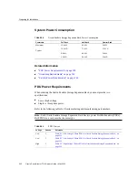
Page 225: ...Install Oracle Configuration Manager on SPARC T5 8 Servers 11 Search for your system in the targets search window at the top right of the screen Monitoring the System 225 ...

Page 226: ...g with Oracle SuperCluster 1 1 you can monitor all Exadata related software and hardware components in the cluster using Oracle Enterprise Manager Exadata 12 1 0 3 Plug in only in the supported configuration described in the note below System Requirements on page 227 Known Issues With EM Exadata Plug in on page 227 226 Oracle SuperCluster T5 8 Owner s Guide May 2016 ...

Page 227: ...data plug in 12 1 0 3 does not support the catalog xml file Download the latest exadataDiscoveryPreCheck pl file from My Oracle Support as described in the Discovery Precheck Script section of the Oracle Enterprise Manager Exadata Management Getting Started Guide http docs oracle com cd E24628_01 doc 121 e27442 title htm If multiple database clusters share the same Exadata Storage server in one En...

Page 228: ...228 Oracle SuperCluster T5 8 Owner s Guide May 2016 ...

Page 229: ...uperCluster T5 8 to improve input output thread management and request handling efficiency Additional optimizations include reduced buffer copies which result in more efficient input output Finally session replication performance and CPU utilization is improved through lazy deserialization which avoids performing extra work on every session update that is only necessary when a server fails WebLogi...

Page 230: ...evel Enhancements To enable domain level enhancements complete the following steps 1 Log in to the Oracle WebLogic Server Administration Console 2 Select Domain name in the left navigation pane The Settings for Domain name screen is displayed Click the General tab 3 In your domain home page select Enable Exalogic Optimizations and click Save 4 Activate changes 5 Stop and start your domain The Enab...

Page 231: ...u will deploy a web application at a later time Note If you are using Coherence web these session replication enhancements do not apply Skip these steps if you use the dizzyworld ear application as described in Chapter 8 Deploying a Sample Web Application to and Oracle WebLogic Cluster in the Oracle Fusion Middleware Exalogic Enterprise Deployment Guide at http docs oracle com cd E18476_01 doc 220...

Page 232: ... in to the Oracle WebLogic Server Administration Console b If you have not already done so click Lock Edit in the Change Center c In the left pane of the Console expand Environment and select Servers The Summary of Servers page is displayed d In the Servers table click WLS1 Managed Server instance e Select Protocols and then Channels f Click New g Enter ReplicationChannel as the name of the new ne...

Page 233: ...ationChannel t3 10 0 0 3 7005 7006 to 7014 WLS4 ReplicationChannel t3 10 0 0 4 7005 7006 to 7014 WLS5 ReplicationChannel t3 10 0 0 5 7005 7006 to 7014 WLS6 ReplicationChannel t3 10 0 0 6 7005 7006 to 7014 WLS7 ReplicationChannel t3 10 0 0 7 7005 7006 to 7014 WLS8 ReplicationChannel t3 10 0 0 8 7005 7006 to 7014 4 After creating the network channel for each of the Managed Servers in your cluster cl...

Page 234: ...Select a Managed Server such as WLS1 by clicking WLS1 The Settings for WLS1 page is displayed c Click the Control tab Select WLS1 in the Server Status table Click Start d Repeat these steps for each of the Managed Servers in the WebLogic cluster Note To verify that multiple listening ports were opened you can either run the netstat na command on the command line or check the Managed Server logs Co...

Page 235: ...o complete before closing connections New requests are load balanced to an active Oracle RAC node Adapt to changes in topology such as adding a new node Distribute runtime work requests to all active Oracle RAC instances See Fast Connection Failover in the Oracle Database JDBC Developer s Guide and Reference at http docs oracle com cd B19306_01 java 102 b14355 fstconfo htm Runtime Connection Load ...

Page 236: ...odes Contact your network administrator for appropriately configured SCAN urls for your environment For more information see http www oracle com technetwork database clustering overview scan 129069 pdf Secure Communication using Oracle Wallet Allows you to configure secure communication with the ONS listener using Oracle Wallet Create a GridLink Data Source on Dept1_Cluster1 1 Log in to the Oracle...

Page 237: ...ataBase Password Enter the password For example myPassword1 Confirm Password and click Next Tip For more information see the Oracle Fusion Middleware Oracle WebLogic Server Administration Console Online Help The console automatically generates the complete JDBC URL For example jdbc oracle thin DESCRIPTION ADDRESS_LIST ADDRESS PROTOCOL TCP HOST left PORT 1234 ADDRESS PROTOCOL TCP HOST right PORT 12...

Page 238: ... JDBC Drivers for Dept1_Cluster1 on page 238 Configuring SDP Enabled JDBC Drivers for Dept1_Cluster1 You must configure SDP enabled JDBC drivers for the Dept1_Cluster1 cluster This section discusses the following topics Configure the Database to Support Infiniband on page 238 Enable SDP Support for JDBC on page 239 Monitor SDP Sockets Using netstat on Oracle Solaris on page 240 Configure the Datab...

Page 239: ...e JDBC URL replace TCP protocol with SDP protocol For example jdbc oracle thin DESCRIPTION ADDRESS PROTOCOL sdp HOST 192 x x x PORT 1522 CONNECT_DATA SERVICE_NAME myservice 3 Manually add the system property Djava net preferIPv4Stack true to the startWebLogic sh script which is located in the bin directory of base_domain using a text editor as follows a Locate the following line in the startWebLog...

Page 240: ...the command line netstat f sdp s l This command displays the status of all SDP sockets established or not as in the following sample output SDP sdpActiveOpens 66357 sdpCurrEstab 748 sdpPrFails 0 sdpRejects 0 sdpOutSegs 39985638793 sdpInDataBytes 9450383834191 sdpOutDataBytes 6228930927986 SDP sdpActiveOpens 0 sdpCurrEstab 0 sdpPrFails 0 sdpRejects 0 sdpInSegs 14547 sdpOutSegs 14525 sdpInDataBytes ...

Page 241: ...e cluster to add the virtual IP addresses you will use for the InfiniBand network Make sure that these IP addresses are not used The following is an example Added for Listener over IB 192 168 10 21 ssc01db01 ibvip mycompany com ssc01db01 ibvip 192 168 10 22 ssc01db02 ibvip mycompany com ssc01db02 ibvip 2 On one of the Database Domains as the root user create a network resource for the InfiniBand n...

Page 242: ...min directory The TNSNAMES ORA entries must exist in the GRID_HOME The following example first updates tnsnames ora Complete this step on each Database Domain in the cluster with the correct IP addresses for that Database Domain LISTENER_IBREMOTE should list all other Database Domains that are in the cluster DBM_IB should list all Database Domains in the cluster Note The TNSNAMES entry is only rea...

Page 243: ...0101 vip mycompany com PORT 1521 LISTENER_IPREMOTE DESCRIPTION ADDRESS_LIST ADDRESS PROTOCOL TCP HOST ssc01 scan mycompany com PORT 1521 7 Modify the listener_networks init parameter Connect to the database instance as sysdba SQLPLUS alter system set listener_networks NAME network2 LOCAL_LISTENER LISTENER_IBLOCAL REMOTE_LISTENER LISTENER_IBREMOTE NAME network1 LOCAL_LISTENER LISTENER_IPLOCAL REMOT...

Page 244: ...244 Oracle SuperCluster T5 8 Owner s Guide May 2016 ...

Page 245: ...fying InfiniBand Fabric Connections on page 253 The Ethernet Management Switch also connects to the servers listed below For 1 Gb s Cat 5E cabling information see Ethernet Management Switch Connections on page 256 The following figures are in this section Sun Datacenter InfiniBand Switch 36 Figure 24 Sun Datacenter InfiniBand Switch 36 on page 246 IB Spine Switch slot U1 IB Leaf Switch No 1 slot U...

Page 246: ... No 5 slot 35 Full Rack only Exadata Storage Server No 6 slot 37 Full Rack only Exadata Storage Server No 7 slot 39 Full Rack only Exadata Storage Server No 8 slot 41 Full Rack only The Ethernet Management Switch Figure 30 Ethernet Management Switch Cisco Catalyst 4948 Ethernet Switch on page 251 PDU circuit breakers and AC sockets Figure 31 Circuit Breakers and AC Sockets on the PDU on page 252 F...

Page 247: ...rd Locations Full Rack Figure Legend 1 Dual port 10 GbE network interface cards for connection to the 10 GbE client access network 2 Dual port InfiniBand host channel adapters for connection to the InfiniBand network Understanding Internal Cabling 247 ...

Page 248: ...ions Half Rack Figure Legend 1 Dual port 10 GbE network interface cards for connection to the 10 GbE client access network 2 Dual port InfiniBand host channel adapters for connection to the InfiniBand network 248 Oracle SuperCluster T5 8 Owner s Guide May 2016 ...
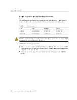
Page 249: ...Port Locations on the SPARC T5 8 Server Figure Legend 1 NET MGT port for connection to Oracle ILOM management network 2 NET0 NET3 ports for connection to 1 GbE host management network FIGURE 28 ZFS Storage Controller Understanding Internal Cabling 249 ...

Page 250: ...ent port 5 Service processor network management port 6 Gigabit Ethernet ports NET 0 1 2 3 7 USB ports 0 1 8 HD15 video connector FIGURE 29 Exadata Storage Server Figure Legend 1 Power supply 1 2 Power supply 2 3 System status LEDs 4 Serial management port 250 Oracle SuperCluster T5 8 Owner s Guide May 2016 ...
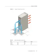
Page 251: ...ector FIGURE 30 Ethernet Management Switch Cisco Catalyst 4948 Ethernet Switch Figure Legend 1 Indicators and reset switch 2 Ports 1 16 10 100 1000BASE T Ethernet 3 Ports 17 32 10 100 1000BASE T Ethernet 4 Ports 33 48 10 100 1000BASE T Ethernet 5 CON upper MGT lower 6 Ports 45 48 10 Gigabit Ethernet Understanding Internal Cabling 251 ...

Page 252: ...Connector Locations FIGURE 31 Circuit Breakers and AC Sockets on the PDU Figure Legend 1 PDU A 252 Oracle SuperCluster T5 8 Owner s Guide May 2016 ...

Page 253: ...ne Switch Port To Device Device Location Device Port U1 1B Leaf switch 1 U26 8B U1 0B Leaf switch 2 U32 8B IB Leaf Switch No 1 Leaf Switch 1 Port To Device Device Location Device Port U26 0A T5 8 No 2 U18 PCIE 16 P2 U26 0B T5 8 No 2 Full Rack U18 PCIE 15 P2 U26 1A T5 8 No 2 U18 PCIE 8 P2 U26 1B T5 8 No 2 Full Rack U18 PCIE 7 P2 U26 2A U26 2B U26 3A ZFS storage controller No 2 U34 PCIE 0 P1 U26 3B ...

Page 254: ...B IB leaf switch 2 U32 11A U26 12A Exadata Storage Server No 7 Full Rack U39 PCIE 3 P1 U26 12B T5 8 No 1 Full Rack U10 PCIE 12 P1 U26 13A T5 8 No 1 U10 PCIE 11 P1 U26 13B T5 8 No 1 Full Rack U10 PCIE 4 P1 U26 14A T5 8 No 1 U10 PCIE 3 P1 U26 14B ZFS storage controller No 1 U33 PCIE 0 P1 U26 15A Exadata Storage Server No 6 Full Rack U37 PCIE 3 P2 U26 15B Exadata Storage Server No 5 Full Rack U35 PCI...

Page 255: ...l Rack U41 PCIE 3 P1 U32 8A IB leaf switch No 1 U26 8A U32 8B IB spine switch U1 0B U32 9A IB leaf switch No 1 U26 9B U32 9B IB leaf switch No 1 U26 9A U32 10A IB leaf switch No 1 U26 10B U32 10B IB leaf switch No 1 U26 10A U32 11A IB leaf switch No 1 U26 11B U32 11B IB leaf switch No 1 U26 11A U32 12A Exadata Storage Server No 7 Full Rack U39 PCIE 3 P2 U32 12B T5 8 No 1 Full Rack U10 PCIE 12 P2 U...

Page 256: ...hrough the ports listed in the following tables The following table lists the cables for the Ethernet Management switch Note Ethernet management switch port numbers 45 46 47 and 48 are shared between item 4 10BASE T 100BASE TX 1000BASE T Ethernet and item 6 1000BASE X Ethernet Note Ethernet management switch ports 1 2 3 and 4 are not used at this time Ethernet Switch Port To Device Device Location...

Page 257: ... 1 U33 NET 2 Blue 10 ft 33 Exadata Storage Server No 6 Full Rack U37 NET 0 Black 10 ft 34 Exadata Storage Server No 6 Full Rack U37 NET MGT Red 10 ft 35 Exadata Storage Server No 5 Full Rack U35 NET 0 Black 10 ft 36 Exadata Storage Server No 5 Full Rack U35 NET MGT Red 10 ft 37 Exadata Storage Server No 4 U8 NET 0 Black 10 ft 38 Exadata Storage Server No 4 U8 NET MGT Red 10 ft 39 Exadata Storage S...

Page 258: ...le phase AC power connect the devices in the rack to the power distribution unit PDU as shown in the following table Each device requires two power cords for redundant power Caution Turn off all PDU circuit breakers before connecting power cords to the PDU Every socket group has a circuit breaker See Figure 31 Circuit Breakers and AC Sockets on the PDU on page 252 for the locations of the PDU circ...

Page 259: ...a Storage Server No 3 U4 Group 0 2 Group 5 4 Exadata Storage Server No 2 U2 Group 0 1 Group 5 5 Exadata Storage Server No 1 U1 Group 0 0 Group 5 6 Sun Datacenter InfiniBand Switch 36 Spine Switch Three Phase PDU Cabling For three phase AC power connect the devices in the rack to the power distribution units PDUs as shown in the following table Each device requires two power cords for redundant pow...

Page 260: ...ch No 2 U28 Group 4 6 Group 1 0 Sun Disk Shelf U27 Group 3 5 Group 0 1 Ethernet management switch U26 Group 3 6 Group 0 0 Sun Datacenter InfiniBand Switch 36 Leaf Switch No 1 U18 Group 3 7 Group 0 7 Group 4 7 Group 1 7 SPARC T5 8 No 2 U10 Group 1 7 Group 4 7 Group 2 7 Group 5 7 SPARC T5 8 No 1 U8 Group 0 4 Group 3 2 Exadata Storage Server No 4 U6 Group 0 3 Group 3 3 Exadata Storage Server No 3 U4 ...

Page 261: ...le SuperCluster T5 8 includes three Sun Datacenter InfiniBand Switch 36 switches These switches attach to standard Quad Small Form factor Pluggable QSFP connectors at the end of the InfiniBand cables The procedures in this section assume the racks are adjacent to each other If they are not then longer cables may be required for the connections The switch at rack unit 1 U1 is referred to as the spi...

Page 262: ...as well as the two connections between the leaf switches and the spine switch From each leaf switch distribute eight connections over the spine switches in all racks In multi rack environments the leaf switches inside a rack are no longer directly interconnected as shown in the following graphic 262 Oracle SuperCluster T5 8 Owner s Guide May 2016 ...

Page 263: ...owing switches Eight connections to both internal leaf switches Eight connections to both leaf switches in rack 2 In Oracle SuperCluster T5 8 the spine and leaf switches are installed in the following locations Spine switch in U1 Two leaf switches in U26 and U32 Two Rack Cabling The following table shows the cable connections for the first spine switch R1 U1 when cabling two full racks together Co...

Page 264: ...26 to Rack 2 R1 U26 P10A to R2 U1 P7B R1 U26 P10B to R2 U1 P8B R1 U26 P11A to R2 U1 P9B R1 U26 P11B to R2 U1 P10B 5 meters The following table shows the cable connections for the second spine switch R2 U1 when cabling two full racks together TABLE 23 Leaf Switch Connections for the Second Rack in a Two Rack System Leaf Switch Connection Cable Length R2 U32 within Rack 2 R2 U32 P8A to R2 U1 P3A R2 ...

Page 265: ...ck System Leaf Switch Connection Cable Length R1 U32 within Rack 1 R1 U32 P8A to R1 U1 P3A R1 U32 P8B to R1 U1 P4A R1 U32 P9A to R1 U1 P5A 5 meters R1 U32 to Rack 2 R1 U32 P9B to R2 U1 P6A R1 U32 P10A to R2 U1 P7A R1 U32 P10B to R2 U1 P8A 5 meters R1 U32 to Rack 3 R1 U32 P11A to R3 U1 P9A R1 U32 P11B to R3 U1 P10A 5 meters R1 U26 within Rack 1 R1 U26 P8A to R1 U1 P3B R1 U26 P8B to R1 U1 P4B R1 U26...

Page 266: ...B R2 U26 P8B to R2 U1 P4B R2 U26 P9A to R2 U1 P5B 5 meters R2 U26 to Rack 1 R2 U26 P11A to R1 U1 P9B R2 U26 P11B to R1 U1 P10B 5 meters R2 U26 to Rack 3 R2 U26 P9B to R3 U1 P6B R2 U26 P10A to R3 U1 P7B R2 U26 P10B to R3 U1 P8B 5 meters The following table shows the cable connections for the third spine switch R3 U1 when cabling three full racks together TABLE 26 Leaf Switch Connections for the Thi...

Page 267: ...tions for the First Rack in a Four Rack System Leaf Switch Connection Cable Length R1 U32 within Rack 1 R1 U32 P8A to R1 U1 P3A R1 U32 P8B to R1 U1 P4A 5 meters R1 U32 to Rack 2 R1 U32 P9A to R2 U1 P5A R1 U32 P9B to R2 U1 P6A 5 meters R1 U32 to Rack 3 R1 U32 P10A to R3 U1 P7A R1 U32 P10B to R3 U1 P8A 5 meters R1 U32 to Rack 4 R1 U32 P11A to R4 U1 P9A R1 U32 P11B to R4 U1 P10A 10 meters R1 U26 with...

Page 268: ... P7A R2 U32 P10B to R4 U1 P8A 5 meters R2 U26 within Rack 2 R2 U26 P8A to R2 U1 P3B R2 U26 P8B to R2 U1 P4B 5 meters R2 U26 to Rack 1 R2 U26 P11A to R1 U1 P9B R2 U26 P11B to R1 U1 P10B 5 meters R2 U26 to Rack 3 R2 U26 P9A to R3 U1 P5B R2 U26 P9B to R3 U1 P6B 5 meters R2 U26 to Rack 4 R2 U26 P10A to R4 U1 P7B R2 U26 P10B to R4 U1 P8B 5 meters The following table shows the cable connections for the ...

Page 269: ... when cabling four full racks together TABLE 30 Leaf Switch Connections for the Fourth Rack in a Four Rack System Leaf Switch Connection Cable Length R4 U32 within Rack 4 R4 U32 P8A to R4 U1 P3A R4 U32 P8B to R4 U1 P4A 5 meters R4 U32 to Rack 1 R4 U32 P9A to R1 U1 P5A R4 U32 P9B to R1 U1 P6A 10 meters R4 U32 to Rack 2 R4 U32 P10A to R2 U1 P7A R4 U32 P10B to R2 U1 P8A 5 meters R4 U32 to Rack 3 R4 U...

Page 270: ...32 P11A to R4 U1 P9A 10 meters R1 U32 to Rack 5 R1 U32 P11B to R5 U1 P10A 10 meters R1 U26 within Rack 1 R1 U26 P8A to R1 U1 P3B R1 U26 P8B to R1 U1 P4B 3 meters R1 U26 to Rack 2 R1 U26 P9A to R2 U1 P5B R1 U26 P9B to R2 U1 P6B 3 meters R1 U26 to Rack 3 R1 U26 P10A to R3 U1 P7B R1 U26 P10B to R3 U1 P8B 5 meters R1 U26 to Rack 4 R1 U26 P11A to R4 U1 P9B 10 meters R1 U26 to Rack 5 R1 U26 P11B to R5 U...

Page 271: ...able shows the cable connections for the third spine switch R3 U1 when cabling five full racks together TABLE 33 Leaf Switch Connections for the Third Rack in a Five Rack System Leaf Switch Connection Cable Length R3 U32 within Rack 3 R3 U32 P8A to R3 U1 P3A R3 U32 P8B to R3 U1 P4A 3 meters R3 U32 to Rack 1 R3 U32 P11A to R1 U1 P9A 5 meters R3 U32 to Rack 2 R3 U32 P11B to R2 U1 P10A 5 meters R3 U3...

Page 272: ...rs R4 U32 to Rack 5 R4 U32 P9A to R5 U1 P5A R4 U32 P9B to R5 U1 P6A 5 meters R4 U26 within Rack 4 R4 U26 P8A to R4 U1 P3B R4 U26 P8B to R4 U1 P4B 3 meters R4 U26 to Rack 1 R4 U26 P10A to R1 U1 P7B R4 U26 P10B to R1 U1 P8B 10 meters R4 U26 to Rack 2 R4 U26 P11A to R2 U1 P9B 5 meters R4 U26 to Rack 3 R4 U26 P11B to R3 U1 P10B 5 meters R4 U26 to Rack 5 R4 U26 P9A to R5 U1 P5B R4 U26 P9B to R5 U1 P6B ...

Page 273: ...abling The following table shows the cable connections for the first spine switch R1 U1 when cabling six full racks together TABLE 36 Leaf Switch Connections for the First Rack in a Six Rack System Leaf Switch Connection Cable Length R1 U32 within Rack 1 R1 U32 P8A to R1 U1 P3A R1 U32 P8B to R1 U1 P4A 3 meters R1 U32 to Rack 2 R1 U32 P9A to R2 U1 P5A R1 U32 P9B to R2 U1 P6A 5 meters R1 U32 to Rack...

Page 274: ... P6A 5 meters R2 U32 to Rack 4 R2 U32 P10A to R4 U1 P7A 5 meters R2 U32 to Rack 5 R2 U32 P10B to R5 U1 P8A 10 meters R2 U32 to Rack 6 R2 U32 P11Ato R6 U1 P9A 10 meters R2 U26 within Rack 2 R2 U26 P8A to R2 U1 P3B R2 U26 P8B to R2 U1 P4B 3 meters R2 U26 to Rack 1 R2 U26 P11B to R1 U1 P10B 5 meters R2 U26 to Rack 3 R2 U26 P9A to R3 U1 P5B R2 U26 P9B to R3 U1 P6B 5 meters R2 U26 to Rack 4 R2 U26 P10A...

Page 275: ...cable connections for the fourth spine switch R4 U1 when cabling six full racks together TABLE 39 Leaf Switch Connections for the Fourth Rack in a Six Rack System Leaf Switch Connection Cable Length R4 U32 within Rack 4 R4 U32 P8A to R4 U1 P3A R4 U32 P8B to R4 U1 P4A 3 meters R4 U32 to Rack 1 R4 U32 P10B to R1 U1 P8A 10 meters R4 U32 to Rack 2 R4 U32 P11A to R2 U1 P9A 5 meters R4 U32 to Rack 3 R4 ...

Page 276: ...9B to R6 U1 P6A 5 meters R5 U26 within Rack 5 R5 U26 P8A to R5 U1 P3B R5 U26 P8B to R5 U1 P4B 3 meters R5 U26 to Rack 1 R5 U26 P10A to R1 U1 P7B 10 meters R5 U26 to Rack 2 R5 U26 P10B to R2 U1 P8B 10 meters R5 U26 to Rack 3 R5 U26 P11A to R3 U1 P9B 5 meters R5 U26 to Rack 4 R5 U26 P11B to R4 U1 P10B 5 meters R5 U26 to Rack 6 R5 U26 P9A to R6 U1 P5B R5 U26 P9B to R6 U1 P6B 5 meters The following ta...

Page 277: ...itch Connections for the First Rack in a Seven Rack System Leaf Switch Connection Cable Length R1 U32 within Rack 1 R1 U32 P8A to R1 U1 P3A R1 U32 P8B to R1 U1 P4A 3 meters R1 U32 to Rack 2 R1 U32 P9A to R2 U1 P5A 5 meters R1 U32 to Rack 3 R1 U32 P9B to R3 U1 P6A 5 meters R1 U32 to Rack 4 R1 U32 P10A to R4 U1 P7A 10 meters R1 U32 to Rack 5 R1 U32 P10B to R5 U1 P8A 10 meters R1 U32 to Rack 6 R1 U32...

Page 278: ...3 R2 U26 P9A to R3 U1 P5B 5 meters R2 U26 to Rack 4 R2 U26 P9B to R4 U1 P6B 5 meters R2 U26 to Rack 5 R2 U26 P10A to R5 U1 P7B 10 meters R2 U26 to Rack 6 R2 U26 P10Bto R6 U1 P8B 10 meters R2 U26 to Rack 7 R2 U26 P11A to R7 U1 P9B 10 meters The following table shows the cable connections for the third spine switch R3 U1 when cabling seven full racks together TABLE 44 Leaf Switch Connections for the...

Page 279: ...A to R2 U1 P9A 5 meters R4 U32 to Rack 3 R4 U32 P11B to R3 U1 P10A 5 meters R4 U32 to Rack 5 R4 U32 P9A to R5 U1 P5A 5 meters R4 U32 to Rack 6 R4 U32 P9B to R6 U1 P6A 5 meters R4 U32 to Rack 7 R4 U32 P10A to R7 U1 P7A 10 meters R4 U26 within Rack 4 R4 U26 P8A to R4 U1 P3B R4 U26 P8B to R4 U1 P4B 3 meters R4 U26 to Rack 1 R4 U26 P10B to R1 U1 P8B 10 meters R4 U26 to Rack 2 R4 U26 P11A to R2 U1 P9B ...

Page 280: ...able shows the cable connections for the sixth spine switch R6 U1 when cabling seven full racks together TABLE 47 Leaf Switch Connections for the Sixth Rack in a Seven Rack System Leaf Switch Connection Cable Length R6 U32 within Rack 6 R6 U32 P8A to R6 U1 P3A R6 U32 P8B to R6 U1 P4A 3 meters R6 U32 to Rack 1 R6 U32 P9B to R1 U1 P6A 10 meters R6 U32 to Rack 2 R6 U32 P10A to R2 U1 P7A 10 meters R6 ...

Page 281: ... P10A 5 meters R7 U26 within Rack 7 R7 U26 P8A to R7 U1 P3B R7 U26 P8B to R7 U1 P4B 3 meters R7 U26 to Rack 1 R7 U26 P9A to R1 U1 P5B 10 meters R7 U26 to Rack 2 R7 U26 P9B to R2 U1 P6B 10 meters R7 U26 to Rack 3 R7 U26 P10A to R3 U1 P7B 10 meters R7 U26 to Rack 4 R7 U26 P10B to R4 U1 P8B 10 meters R7 U26 to Rack 5 R7 U26 P11A to R5 U1 P9B 5 meters R7 U26 to Rack 6 R7 U26 P11B to R6 U1 P10B 5 meter...

Page 282: ... an Eight Rack System Leaf Switch Connection Cable Length R2 U32 within Rack 2 R2 U32 P8A to R2 U1 P3A 3 meters R2 U32 to Rack 1 R2 U32 P11B to R1 U1 P10A 5 meters R2 U32 to Rack 3 R2 U32 P8B to R3 U1 P4A 5 meters R2 U32 to Rack 4 R2 U32 P9A to R4 U1 P5A 5 meters R2 U32 to Rack 5 R2 U32 P9B to R5 U1 P6A 10 meters R2 U32 to Rack 6 R2 U32 P10A to R6 U1 P7A 10 meters R2 U32 to Rack 7 R2 U32 P10B to R...

Page 283: ...to Rack 7 R3 U26 P10A to R7 U1 P7B 10 meters R3 U26 to Rack 8 R3 U26 P10B to R8 U1 P8B 10 meters The following table shows the cable connections for the fourth spine switch R4 U1 when cabling eight full racks together TABLE 52 Leaf Switch Connections for the Fourth Rack in an Eight Rack System Leaf Switch Connection Cable Length R4 U32 within Rack 4 R4 U32 P8A to R4 U1 P3A 3 meters R4 U32 to Rack ...

Page 284: ...5 U32 to Rack 8 R5 U32 P9B to R8 U1 P6A 10 meters R5 U26 within Rack 5 R5 U26 P8A to R5 U1 P3B 3 meters R5 U26 to Rack 1 R5 U26 P10A to R1 U1 P7B 10 meters R5 U26 to Rack 2 R5 U26 P10B to R2 U1 P8B 10 meters R5 U26 to Rack 3 R5 U26 P11A to R3 U1 P9B 5 meters R5 U26 to Rack 4 R5 U26 P11B to R4 U1 P10B 5 meters R5 U26 to Rack 6 R5 U26 P8B to R6 U1 P4B 5 meters R5 U26 to Rack 7 R5 U26 P9A to R7 U1 P5...

Page 285: ...h Connection Cable Length R7 U32 within Rack 7 R7 U32 P8A to R7 U1 P3A 3 meters R7 U32 to Rack 1 R7 U32 P9A to R1 U1 P5A 10 meters R7 U32 to Rack 2 R7 U32 P9B to R2 U1 P6A 10 meters R7 U32 to Rack 3 R7 U32 P10A to R3 U1 P7A 10 meters R7 U32 to Rack 4 R7 U32 P10B to R4 U1 P8A 10 meters R7 U32 to Rack 5 R7 U32 P11A to R5 U1 P9A 5 meters R7 U32 to Rack 6 R7 U32 P11B to R6 U1 P10A 5 meters R7 U32 to R...

Page 286: ...ck 5 R8 U32 P10B to R5 U1 P8A 5 meters R8 U32 to Rack 6 R8 U32 P11A to R6 U1 P9A 5 meters R8 U32 to Rack 7 R8 U32 P11B to R7 U1 P10A 5 meters R8 U26 within Rack 8 R8 U26 P8A to R8 U1 P3B 3 meters R8 U26 to Rack 1 R8 U26 P8B to R1 U1 P4B 10 meters R8 U26 to Rack 2 R8 U26 P9A to R2 U1 P5B 10 meters R8 U26 to Rack 3 R8 U26 P9B to R3 U1 P6B 10 meters R8 U26 to Rack 4 R8 U26 P10A to R4 U1 P7B 10 meters...

Page 287: ... Oracle Exadata Storage Expansion Racks can be used to add space to Oracle SuperCluster T5 8 as follows Add new Exadata Storage Servers and grid disks to a new Oracle Automatic Storage Management Oracle ASM disk group Extend existing disk groups by adding grid disks in Oracle Exadata Storage Expansion Rack Split Oracle Exadata Storage Expansion Rack among multiple Oracle SuperCluster T5 8 systems ...

Page 288: ...t Cisco Catalyst 4948 model number WS C4948 S Ethernet switch 600 GB 15 K RPM High Performance SAS disks or 3 TB 7 2 K RPM High Capacity SAS disks first Exadata Storage Server type or 1 2 TB 10 K RPM High Performance SAS disks or 4 TB 7 2 K RPM High Capacity SAS disks second Exadata Storage Server type 2 Sun Datacenter InfiniBand Switch 36 High speed flash 6 4 TB of raw flash capacity first Exadat...

Page 289: ... 1200 mm 47 24 in Depth without doors 1112 mm 43 78 in Minimum ceiling height 2300 mm 90 in Minimum space between top of cabinet and ceiling 914 mm 36 in Weight full rack 917 6 kg 2023 lbs Weight half rack 578 3 kg 1275 lbs Weight quarter rack 396 8 kg 875 lbs Related Information Installation and Service Area on page 96 Rack and Floor Cutout Dimensions on page 97 Reviewing Power Requirements Syste...

Page 290: ... you must provide two specifications Low or high voltage Single or three phase power Refer to the following tables for Oracle marketing and manufacturing part numbers Note Each Oracle Exadata Storage Expansion Rack has two power distribution units PDUs Both PDUs in a rack must be the same type TABLE 60 PDU Choices Voltage Phases Reference Low 1 Table 61 Low Voltage 1 Phase PDUs for Oracle Exadata ...

Page 291: ...ata center receptacle NEMA 30A 250 VAC 2 pole 3 wire L6 30P Outlet groups per PDU 6 Usable PDU power cord length 2 m 6 6 feet PDU power cords are 4 m long 13 feet but sections are used for internal routing in the rack TABLE 62 Low Voltage 3 Phase PDUs for Oracle Exadata Storage Expansion Rack High Voltage Three Phase Comments kVA Size 14 4 kVA Marketing part number N A Manufacturing part number N ...

Page 292: ...x per input Data center receptacle IEC 60309 32A 3 pin 250VAC IP44 Outlet groups per PDU 6 Usable PDU power cord length 2 m 6 6 feet PDU power cords are 4 m long 13 feet but sections are used for internal routing in the rack TABLE 64 High Voltage 3 Phase PDUs for Oracle Exadata Storage Expansion Rack High Voltage Single Phase Comments kVA size 14 4 kVA Marketing part number N A Manufacturing part ...

Page 293: ...sts temperature humidity and altitude requirements TABLE 65 Temperature Humidity and Altitude Condition Operating Requirement Non operating Requirement Comments Temperature 5 to 32 C 41 to 89 6 F 40 to 70 C 40 to 158 F For optimal rack cooling data center temperatures from 21 to 23 C 70 to 47 F Relative humidity 10 to 90 relative humidity noncondensing Up to 93 relative humidity For optimal data c...

Page 294: ... 400 Quarter rack BTU hour kJ hour 11 600 12 250 8 100 8 600 Caution Do not restrict the movement of cool air from the air conditioner to the cabinet or the movement of hot air out of the rear of the cabinet Observe these additional requirements Allow a minimum clearance of 914 mm 36 inches at the front of the rack and 914 mm 36 inches at the rear of the rack for ventilation There is no airflow re...

Page 295: ...n FIGURE 32 Direction of Airflow Is Front to Back TABLE 67 Airflow listed quantities are approximate Rack Maximum Typical Full rack CFM 2 000 1 390 Half rack CFM 1 090 760 Quarter rack CFM 530 375 Connecting Expansion Racks 295 ...

Page 296: ... as long as cold air from the tiles can flow into the rack The following is the recommended number of floor tiles TABLE 68 Perforated Floor Tile Requirements Rack Number of Tiles Full rack 4 Half rack 3 Quarter rack 2 Related Information Heat Dissipation and Airflow Requirements on page 294 Environmental Requirements on page 293 Preparing the Unloading Route and Unpacking Area Shipping Package Dim...

Page 297: ...em on page 114 Network Requirements Overview on page 297 Network Connection and IP Address Requirements on page 299 Network Requirements Overview The Oracle Exadata Storage Expansion Rack includes Exadata Storage Servers as well as equipment to connect the servers to your network The network connections enable the servers to be administered remotely Each Exadata Storage Server consists of the foll...

Page 298: ...d to the Ethernet switch in the rack There is one uplink from the Ethernet switch in the rack to your existing management network Note Network connectivity to the PDUs is only required if the electric current will be monitored remotely Each Exadata Storage Server use two network interfaces for management One provides management access to the operating system through the 1 GbE host management inter...

Page 299: ...ta Storage Server 4 for switches 3 for InfiniBand and 1 for Ethernet 2 for monitoring electric current of the PDUs PDU connectivity is only required if the electric current will be monitored remotely Quarter expansion rack 13 4 for administration one per Exadata Storage Server 4 for Oracle ILOM one per Exadata Storage Server 3 for switches 2 for InfiniBand and 1 for Ethernet 2 for monitoring elect...

Page 300: ... 1 160 192 168 10 60 Exadata Storage Server 9 192 168 1 59 192 168 1 159 192 168 10 59 Exadata Storage Server 8 192 168 1 58 192 168 1 158 192 168 10 58 Exadata Storage Server 7 192 168 1 57 192 168 1 157 192 168 10 57 Exadata Storage Server 6 192 168 1 56 192 168 1 156 192 168 10 56 Exadata Storage Server 5 192 168 1 55 192 168 1 155 192 168 10 55 Exadata Storage Server 4 192 168 1 54 192 168 1 1...

Page 301: ...g on page 308 Three Phase Power Distribution Unit Cabling on page 309 InfiniBand Network Cabling on page 311 Front and Rear Expansion Rack Layout The following figures show the front and rear views of the expansion rack Figure 33 Expansion Rack Layout Full Rack on page 302 Figure 34 Expansion Rack Layout Half Rack on page 303 Figure 35 Expansion Rack Layout Quarter Rack on page 304 Connecting Expa...

Page 302: ...Understanding Expansion Rack Internal Cabling FIGURE 33 Expansion Rack Layout Full Rack 302 Oracle SuperCluster T5 8 Owner s Guide May 2016 ...

Page 303: ...Understanding Expansion Rack Internal Cabling FIGURE 34 Expansion Rack Layout Half Rack Connecting Expansion Racks 303 ...

Page 304: ...ack Oracle ILOM Cabling This topic contains tables that list the Oracle ILOM network cabling The Oracle ILOM port on the servers is labeled NET MGT and connects to the Gigabit Ethernet port located in rack unit 21 on the expansion racks 304 Oracle SuperCluster T5 8 Owner s Guide May 2016 ...

Page 305: ...9 Exadata Storage Server 14 U27 Exadata Storage Server 18 U25 Exadata Storage Server 22 U18 Exadata Storage Server 26 U16 Exadata Storage Server 30 U14 Exadata Storage Server 32 U12 Exadata Storage Server 34 U10 Exadata Storage Server 36 U8 Exadata Storage Server 38 U6 Exadata Storage Server 40 U4 Exadata Storage Server 42 U2 Exadata Storage Server 44 TABLE 72 Oracle ILOM Cabling for the Expansion...

Page 306: ...75 Gigabit Ethernet Cabling for the Expansion Rack Half Rack on page 307 Table 75 Gigabit Ethernet Cabling for the Expansion Rack Half Rack on page 307 TABLE 74 Gigabit Ethernet Cabling for the Expansion Rack Full Rack From Rack Unit Type of Equipment Gigabit Ethernet Port U41 Exadata Storage Server 1 U39 Exadata Storage Server 3 U37 Exadata Storage Server 5 U35 Exadata Storage Server 7 U33 Exadat...

Page 307: ... Storage Server 25 U16 Exadata Storage Server 29 U14 Exadata Storage Server 31 U12 Exadata Storage Server 33 U10 Exadata Storage Server 35 U8 Exadata Storage Server 37 U6 Exadata Storage Server 39 U4 Exadata Storage Server 41 U2 Exadata Storage Server 43 U1 Sun Datacenter InfiniBand Switch 36 switch 47 PDU A PDU 15 PDU B PDU 19 TABLE 76 Gigabit Ethernet Cabling for the Expansion Rack Quarter Rack ...

Page 308: ...ter Rack on page 309 TABLE 77 Single Phase PDU Cabling for the Expansion Rack Full Rack Rack Unit PDU A PS 00 PDU B PS 01 Cable Length U41 G5 6 G0 0 2 meters U39 G5 3 G0 3 2 meters U37 G5 0 G0 6 2 meters U35 G4 6 G1 0 2 meters U33 G4 4 G1 2 2 meters U31 G4 2 G1 4 2 meters U29 G3 6 G2 0 2 meters U27 G3 5 G2 1 2 meters U25 G3 3 G2 3 2 meters U24 G3 1 G2 5 2 meters U23 N A G3 0 included U22 G2 5 G3 1...

Page 309: ...k Quarter Rack Rack Unit PDU A PS 00 PDU B PS 01 Cable Length U24 G3 1 G2 5 2 meters U23 N A G3 0 included U22 G2 5 G3 1 1 meter U21 G3 0 G2 6 2 meters U20 G2 4 G3 2 2 meters U8 G1 0 G4 6 2 meters U6 G0 6 G5 0 2 meters U4 G0 4 G5 2 2 meters U2 G0 2 G5 4 2 meters Three Phase Power Distribution Unit Cabling This topic contains tables that list the three phase cabling from each PDU to the power suppl...

Page 310: ... 3 G0 3 2 meters U24 G3 1 G0 5 2 meters U23 N A G5 0 included U22 G2 5 G5 1 1 meter U21 G3 0 G0 6 2 meters U20 G2 4 G5 2 2 meters U18 G2 2 G5 4 2 meters U16 G1 6 G4 0 2 meters U14 G2 0 G5 6 2 meters U12 G1 4 G4 2 2 meters U10 G1 2 G4 4 2 meters U8 G1 0 G4 6 2 meters U6 G0 6 G3 0 2 meters U4 G0 4 G3 2 2 meters U2 G0 2 G3 4 2 meters U1 G0 0 G3 6 2 meters TABLE 81 Three Phase PDU Cabling for the Expa...

Page 311: ...eters U23 N A G5 0 included U22 G2 5 G5 1 1 meter U21 G3 0 G0 6 2 meters U20 G2 4 G5 2 2 meters U8 G1 0 G4 6 2 meters U6 G0 6 G3 0 2 meters U4 G0 4 G3 2 2 meters U2 G0 2 G3 4 2 meters InfiniBand Network Cabling This topic contains tables that list the InfiniBand network cabling The Sun Datacenter InfiniBand Switch 36 switches are located in located in rack unit 1 20 and 24 Table 82 Three Phase PDU...

Page 312: ...16B U6 Exadata Storage Server PCIe 3 P2 3 meter QDR InfiniBand cable U24 17A U4 Exadata Storage Server PCIe 3 P2 3 meter QDR InfiniBand cable U24 17B U2 Exadata Storage Server PCIe 3 P2 3 meter QDR InfiniBand cable U20 0A U41 Exadata Storage Server PCIe 3 P2 3 meter QDR InfiniBand cable U20 0B U39 Exadata Storage Server PCIe 3 P2 3 meter QDR InfiniBand cable U20 1A U37 Exadata Storage Server PCIe ...

Page 313: ...tch Rack Unit Port To Rack Unit Type of Equipment Port Cable Description U24 13A U18 Exadata Storage Server PCIe 2 P2 2 meter QDR InfiniBand cable U24 14A U16 Exadata Storage Server PCIe 2 P2 2 meter QDR InfiniBand cable U24 14B U14 Exadata Storage Server PCIe 3 P2 3 meter QDR InfiniBand cable U24 15A U12 Exadata Storage Server PCIe 3 P2 3 meter QDR InfiniBand cable U24 15B U10 Exadata Storage Ser...

Page 314: ...nfiniBand Switch 36 switch 8B 3 meter QDR InfiniBand cable TABLE 85 InfiniBand Network Cabling for the Expansion Rack Quarter Rack From InfiniBand Switch Rack Unit Port To Rack Unit Type of Equipment Port Cable Description U24 16A U8 Exadata Storage Server PCIe 2 P2 2 meter QDR InfiniBand cable U24 16B U6 Exadata Storage Server PCIe 3 P2 3 meter QDR InfiniBand cable U24 17A U4 Exadata Storage Serv...

Page 315: ...dard Quad Small Form factor Pluggable QSFP connectors at the end of the InfiniBand cables The procedures in this section assume the racks are adjacent to each other If they are not then longer cables may be required for the connections Note The Oracle Exadata Storage Expansion Quarter Rack contains only two Sun Datacenter InfiniBand Switch 36 switches the leaf switches so no spine switch is availa...

Page 316: ...witch except for the Oracle Exadata Storage Expansion Quarter Rack which has no spine switch The switches at rack unit 20 U20 and rack unit 24 U24 are referred to as leaf switches Connecting an Oracle Exadata Storage Expansion Quarter Rack to Oracle SuperCluster T5 8 These topics describe how to connect an Oracle Exadata Storage Expansion Quarter Rack to your Oracle SuperCluster T5 8 316 Oracle Su...

Page 317: ... leaf switch in the Oracle Exadata Storage Expansion Quarter Rack to the leaf switches in the Oracle SuperCluster T5 8 In the Full Rack version of Oracle SuperCluster T5 8 only two ports are open on both leaf switches ports 2A and 2B Therefore if you are connecting an Oracle Exadata Storage Expansion Quarter Rack to the Full Rack version of Oracle SuperCluster T5 8 you must order a spine switch ki...

Page 318: ...no spine switch Half Rack version of Oracle SuperCluster T5 8 Oracle Exadata Storage Expansion Half Rack Oracle Exadata Storage Expansion Full Rack The racks are interconnected using a fat tree topology Each leaf switch in the Oracle Exadata Storage Expansion Quarter Rack connects to the spine switches in the other Half Racks or Full Racks with two links each If there are more than four racks then...

Page 319: ...in Oracle SuperCluster T5 8 InfiniBand 2 IB2 refers to the first leaf switch located in U26 in Oracle SuperCluster T5 8 Half Rack U20 in the Oracle Exadata Storage Expansion Rack InfiniBand 3 IB3 refers to the second leaf switch located in U32 in Oracle SuperCluster T5 8 Half Rack U24 in the Oracle Exadata Storage Expansion Rack The following table shows the cable connections for a single Oracle E...

Page 320: ...ull Rack to your Oracle SuperCluster T5 8 Note For instructions on connecting an Oracle Exadata Storage Expansion Quarter Rack to the Half Rack version of Oracle SuperCluster T5 8 see Connecting an Oracle Exadata Storage Expansion Quarter Rack to Oracle SuperCluster T5 8 on page 316 When connecting multiple racks together remove the seven existing inter switch connections between each leaf switche...

Page 321: ...re used when referring to the two racks Rack 1 R1 refers to Oracle SuperCluster T5 8 Rack 2 R2 refers to the Oracle Exadata Storage Expansion Rack In addition because the InfiniBand switches are physically located in different rack units in the two racks the following terms are used when referring to the InfiniBand switches InfiniBand 1 IB1 refers to the spine switch located in U1 in both racks In...

Page 322: ...Rack Cabling on page 345 Eleven Rack Cabling on page 346 Twelve Rack Cabling on page 347 Thirteen Rack Cabling on page 348 Fourteen Rack Cabling on page 348 Fifteen Rack Cabling on page 349 Sixteen Rack Cabling on page 350 Seventeen Rack Cabling on page 351 Eighteen Rack Cabling on page 351 Two Rack Cabling The following table shows the cable connections for the first spine switch R1 IB1 when cabl...

Page 323: ...cond spine switch R2 IB1 when cabling two racks together TABLE 88 Leaf Switch Connections for the Second Rack in a Two Rack System Leaf Switch Connection Cable Length R2 IB3 within Rack 2 R2 IB3 P8A to R2 IB1 P3A R2 IB3 P8B to R2 IB1 P4A R2 IB3 P9A to R2 IB1 P5A R2 IB3 P9B to R2 IB1 P6A 5 meters R2 IB3 to Rack 1 R2 IB3 P10A to R1 IB1 P7A R2 IB3 P10B to R1 IB1 P8A R2 IB3 P11A to R1 IB1 P9A R2 IB3 P...

Page 324: ... P7A R1 IB3 P10B to R2 IB1 P8A 5 meters R1 IB3 to Rack 3 R1 IB3 P11A to R3 IB1 P9A R1 IB3 P11B to R3 IB1 P10A 5 meters R1 IB2 within Rack 1 R1 IB2 P8A to R1 IB1 P3B R1 IB2 P8B to R1 IB1 P4B R1 IB2 P9A to R1 IB1 P5B 5 meters R1 IB2 to Rack 2 R1 IB2 P9B to R2 IB1 P6B R1 IB2 P10A to R2 IB1 P7B R1 IB2 P10B to R2 IB1 P8B 5 meters R1 IB2 to Rack 3 R1 IB2 P11A to R3 IB1 P9B R1 IB2 P11B to R3 IB1 P10B 5 m...

Page 325: ... P9B to R3 IB1 P6B R2 IB2 P10A to R3 IB1 P7B R2 IB2 P10B to R3 IB1 P8B 5 meters The following table shows the cable connections for the third spine switch R3 IB1 when cabling three full racks together TABLE 91 Leaf Switch Connections for the Third Rack in a Three Rack System Leaf Switch Connection Cable Length R3 IB3 within Rack 3 R3 IB3 P8A to R3 IB1 P3A R3 IB3 P8B to R3 IB1 P4A R3 IB3 P9A to R3 ...

Page 326: ...IB1 P3A R1 IB3 P8B to R1 IB1 P4A 5 meters R1 IB3 to Rack 2 R1 IB3 P9A to R2 IB1 P5A R1 IB3 P9B to R2 IB1 P6A 5 meters R1 IB3 to Rack 3 R1 IB3 P10A to R3 IB1 P7A R1 IB3 P10B to R3 IB1 P8A 5 meters R1 IB3 to Rack 4 R1 IB3 P11A to R4 IB1 P9A R1 IB3 P11B to R4 IB1 P10A 10 meters R1 IB2 within Rack 1 R1 IB2 P8A to R1 IB1 P3B R1 IB2 P8B to R1 IB1 P4B 5 meters R1 IB2 to Rack 2 R1 IB2 P9A to R2 IB1 P5B R1...

Page 327: ...B1 P10B 5 meters R2 IB2 to Rack 3 R2 IB2 P9A to R3 IB1 P5B R2 IB2 P9B to R3 IB1 P6B 5 meters R2 IB2 to Rack 4 R2 IB2 P10A to R4 IB1 P7B R2 IB2 P10B to R4 IB1 P8B 5 meters The following table shows the cable connections for the third spine switch R3 IB1 when cabling four full racks together TABLE 94 Leaf Switch Connections for the Third Rack in a Four Rack System Leaf Switch Connection Cable Length...

Page 328: ...8A to R4 IB1 P3A R4 IB3 P8B to R4 IB1 P4A 5 meters R4 IB3 to Rack 1 R4 IB3 P9A to R1 IB1 P5A R4 IB3 P9B to R1 IB1 P6A 10 meters R4 IB3 to Rack 2 R4 IB3 P10A to R2 IB1 P7A R4 IB3 P10B to R2 IB1 P8A 5 meters R4 IB3 to Rack 3 R4 IB3 P11A to R3 IB1 P9A R4 IB3 P11B to R3 IB1 P10A 5 meters R4 IB2 within Rack 4 R4 IB2 P8A to R4 IB1 P3B R4 IB2 P8B to R4 IB1 P4B 5 meters R4 IB2 to Rack 1 R4 IB2 P9A to R1 I...

Page 329: ...A to R3 IB1 P7B R1 IB2 P10B to R3 IB1 P8B 5 meters R1 IB2 to Rack 4 R1 IB2 P11A to R4 IB1 P9B 10 meters R1 IB2 to Rack 5 R1 IB2 P11B to R5 IB1 P10B 10 meters The following table shows the cable connections for the second spine switch R2 IB1 when cabling five full racks together TABLE 97 Leaf Switch Connections for the Second Rack in a Five Rack System Leaf Switch Connection Cable Length R2 IB3 wit...

Page 330: ...Rack 2 R3 IB3 P11B to R2 IB1 P10A 5 meters R3 IB3 to Rack 4 R3 IB3 P9A to R4 IB1 P5A R3 IB3 P9B to R4 IB1 P6A 5 meters R3 IB3 to Rack 5 R3 IB3 P10A to R5 IB1 P7A R3 IB3 P10B to R5 IB1 P8A 5 meters R3 IB2 within Rack 3 R3 IB2 P8A to R3 IB1 P3B R3 IB2 P8B to R3 IB1 P4B 3 meters R3 IB2 to Rack 1 R3 IB2 P11A to R1 IB1 P9B 5 meters R3 IB2 to Rack 2 R3 IB2 P11B to R2 IB1 P10B 5 meters R3 IB2 to Rack 4 R...

Page 331: ...2 P9A to R5 IB1 P5B R4 IB2 P9B to R5 IB1 P6B 5 meters The following table shows the cable connections for the fifth spine switch R5 IB1 when cabling five full racks together TABLE 100 Leaf Switch Connections for the Fifth Rack in a Five Rack System Leaf Switch Connection Cable Length R5 IB3 within Rack 5 R5 IB3 P8A to R5 IB1 P3A R5 IB3 P8B to R5 IB1 P4A 3 meters R5 IB3 to Rack 1 R5 IB3 P9A to R1 I...

Page 332: ...meters R1 IB3 to Rack 4 R1 IB3 P10B to R4 IB1 P8A 10 meters R1 IB3 to Rack 5 R1 IB3 P11A to R5 IB1 P9A 10 meters R1 IB3 to Rack 6 R1 IB3 P11B to R6 IB1 P10A 10 meters R1 IB2 within Rack 1 R1 IB2 P8A to R1 IB1 P3B R1 IB2 P8B to R1 IB1 P4B 3 meters R1 IB2 to Rack 2 R1 IB2 P9A to R2 IB1 P5B R1 IB2 P9B to R2 IB1 P6B 5 meters R1 IB2 to Rack 3 R1 IB2 P10A to R3 IB1 P7B 5 meters R1 IB2 to Rack 4 R1 IB2 P...

Page 333: ... Rack 6 R2 IB2 P11Ato R6 IB1 P9B 10 meters The following table shows the cable connections for the third spine switch R3 IB1 when cabling six full racks together TABLE 103 Leaf Switch Connections for the Third Rack in a Six Rack System Leaf Switch Connection Cable Length R3 IB3 within Rack 3 R3 IB3 P8A to R3 IB1 P3A R3 IB3 P8B to R3 IB1 P4A 3 meters R3 IB3 to Rack 1 R3 IB3 P11A to R1 IB1 P9A 5 met...

Page 334: ...B3 P9B to R5 IB1 P6A 5 meters R4 IB3 to Rack 6 R4 IB3 P10A to R6 IB1 P7A 5 meters R4 IB2 within Rack 4 R4 IB2 P8A to R4 IB1 P3B R4 IB2 P8B to R4 IB1 P4B 3 meters R4 IB2 to Rack 1 R4 IB2 P10B to R1 IB1 P8B 10 meters R4 IB2 to Rack 2 R4 IB2 P11A to R2 IB1 P9B 5 meters R4 IB2 to Rack 3 R4 IB2 P11B to R3 IB1 P10B 5 meters R4 IB2 to Rack 5 R4 IB2 P9A to R5 IB1 P5B R4 IB2 P9B to R5 IB1 P6B 5 meters R4 I...

Page 335: ...R6 IB1 when cabling six full racks together TABLE 106 Leaf Switch Connections for the Sixth Rack in a Six Rack System Leaf Switch Connection Cable Length R6 IB3 within Rack 6 R6 IB3 P8A to R6 IB1 P3A R6 IB3 P8B to R6 IB1 P4A 3 meters R6 IB3 to Rack 1 R6 IB3 P9A to R1 IB1 P5A R6 IB3 P9B to R1 IB1 P6A 10 meters R6 IB3 to Rack 2 R6 IB3 P10A to R2 IB1 P7A 10 meters R6 IB3 to Rack 3 R6 IB3 P10B to R3 I...

Page 336: ...o R1 IB1 P4B 3 meters R1 IB2 to Rack 2 R1 IB2 P9A to R2 IB1 P5B 5 meters R1 IB2 to Rack 3 R1 IB2 P9B to R3 IB1 P6B 5 meters R1 IB2 to Rack 4 R1 IB2 P10A to R4 IB1 P7B 10 meters R1 IB2 to Rack 5 R1 IB2 P10B to R5 IB1 P8B 10 meters R1 IB2 to Rack 6 R1 IB2 P11A to R6 IB1 P9B 10 meters R1 IB2 to Rack 7 R1 IB2 P11B to R7 IB1 P10B 10 meters The following table shows the cable connections for the second ...

Page 337: ...tion Cable Length R3 IB3 within Rack 3 R3 IB3 P8A to R3 IB1 P3A R3 IB3 P8B to R3 IB1 P4A 3 meters R3 IB3 to Rack 1 R3 IB3 P11A to R1 IB1 P9A 5 meters R3 IB3 to Rack 2 R3 IB3 P11B to R2 IB1 P10A 5 meters R3 IB3 to Rack 4 R3 IB3 P9A to R4 IB1 P5A 5 meters R3 IB3 to Rack 5 R3 IB3 P9B to R5 IB1 P6A 5 meters R3 IB3 to Rack 6 R3 IB3 P10A to R6 IB1 P7A 10 meters R3 IB3 to Rack 7 R3 IB3 P10B to R7 IB1 P8A...

Page 338: ...IB1 P5B 5 meters R4 IB2 to Rack 6 R4 IB2 P9B to R6 IB1 P6B 5 meters R4 IB2 to Rack 7 R4 IB2 P10A to R7 IB1 P7B 10 meters The following table shows the cable connections for the fifth spine switch R5 IB1 when cabling seven full racks together TABLE 111 Leaf Switch Connections for the Fifth Rack in a Seven Rack System Leaf Switch Connection Cable Length R5 IB3 within Rack 5 R5 IB3 P8A to R5 IB1 P3A ...

Page 339: ...9A 5 meters R6 IB3 to Rack 5 R6 IB3 P11B to R5 IB1 P10A 5 meters R6 IB3 to Rack 7 R6 IB3 P9A to R7 IB1 P5A 5 meters R6 IB2 within Rack 6 R6 IB2 P8A to R6 IB1 P3B R6 IB2 P8B to R6 IB1 P4B 3 meters R6 IB2 to Rack 1 R6 IB2 P9B to R1 IB1 P6B 10 meters R6 IB2 to Rack 2 R6 IB2 P10A to R2 IB1 P7B 10 meters R6 IB2 to Rack 3 R6 IB2 P10B to R3 IB1 P8B 5 meters R6 IB2 to Rack 4 R6 IB2 P11A to R4 IB1 P9B 5 me...

Page 340: ... racks together TABLE 114 Leaf Switch Connections for the First Rack in an Eight Rack System Leaf Switch Connection Cable Length R1 IB3 within Rack 1 R1 IB3 P8A to R1 IB1 P3A 3 meters R1 IB3 to Rack 2 R1 IB3 P8B to R2 IB1 P4A 5 meters R1 IB3 to Rack 3 R1 IB3 P9A to R3 IB1 P5A 5 meters R1 IB3 to Rack 4 R1 IB3 P9B to R4 IB1 P6A 10 meters R1 IB3 to Rack 5 R1 IB3 P10A to R5 IB1 P7A 10 meters R1 IB3 to...

Page 341: ...4 R2 IB2 P9A to R4 IB1 P5B 5 meters R2 IB2 to Rack 5 R2 IB2 P9B to R5 IB1 P6B 10 meters R2 IB2 to Rack 6 R2 IB2 P10A to R6 IB1 P7B 10 meters R2 IB2 to Rack 7 R2 IB2 P10B to R7 IB1 P8B 10 meters R2 IB2 to Rack 8 R2 IB2 P11A to R8 IB1 P9B 10 meters The following table shows the cable connections for the third spine switch R3 IB1 when cabling eight full racks together TABLE 116 Leaf Switch Connection...

Page 342: ...Rack 6 R4 IB3 P9A to R6 IB1 P5A 5 meters R4 IB3 to Rack 7 R4 IB3 P9B to R7 IB1 P6A 10 meters R4 IB3 to Rack 8 R4 IB3 P10A to R8 IB1 P7A 10 meters R4 IB2 within Rack 4 R4 IB2 P8A to R4 IB1 P3B 3 meters R4 IB2 to Rack 1 R4 IB2 P10B to R1 IB1 P8B 10 meters R4 IB2 to Rack 2 R4 IB2 P11A to R2 IB1 P9B 5 meters R4 IB2 to Rack 3 R4 IB2 P11B to R3 IB1 P10B 5 meters R4 IB2 to Rack 5 R4 IB2 P8B to R5 IB1 P4B...

Page 343: ...ns for the Sixth Rack in an Eight Rack System Leaf Switch Connection Cable Length R6 IB3 within Rack 6 R6 IB3 P8A to R6 IB1 P3A 3 meters R6 IB3 to Rack 1 R6 IB3 P9B to R1 IB1 P6A 10 meters R6 IB3 to Rack 2 R6 IB3 P10A to R2 IB1 P7A 10 meters R6 IB3 to Rack 3 R6 IB3 P10B to R3 IB1 P8A 5 meters R6 IB3 to Rack 4 R6 IB3 P11A to R4 IB1 P9A 5 meters R6 IB3 to Rack 5 R6 IB3 P11B to R5 IB1 P10A 5 meters R...

Page 344: ...o Rack 6 R7 IB2 P11B to R6 IB1 P10B 5 meters R7 IB2 to Rack 8 R7 IB2 P8B to R8 IB1 P4B 5 meters The following table shows the cable connections for the eighth spine switch R8 IB1 when cabling eight full racks together TABLE 121 Leaf Switch Connections for the Eighth Rack in an Eight Rack System Leaf Switch Connection Cable Length R8 IB3 within Rack 8 R8 IB3 P8A to R8 IB1 P3A 3 meters R8 IB3 to Rac...

Page 345: ...9 IB3 P9A to R2 IB1 P11A R9 IB3 to Rack 3 R9 IB3 P9B to R3 IB1 P11A R9 IB3 to Rack 4 R9 IB3 P10A to R4 IB1 P11A R9 IB3 to Rack 5 R9 IB3 P10B to R5 IB1 P11A R9 IB3 to Rack 6 R9 IB3 P11A to R6 IB1 P11A R9 IB3 to Rack 7 R9 IB3 P11B to R7 IB1 P11A R9 IB3 to Rack 8 R9 IB3 P9A to R8 IB1 P11A R9 IB2 to Rack 1 R9 IB2 P8B to R1 IB1 P11B R9 IB2 to Rack 2 R9 IB2 P9A to R2 IB1 P11B R9 IB2 to Rack 3 R9 IB2 P9B...

Page 346: ... IB2 to Rack 2 R10 IB2 P9A to R2 IB1 P12B R10 IB2 to Rack 3 R10 IB2 P9B to R3 IB1 P12B R10 IB2 to Rack 4 R10 IB2 P10A to R4 IB1 P12B R10 IB2 to Rack 5 R10 IB2 P10B to R5 IB1 P12B R10 IB2 to Rack 6 R10 IB2 P12A to R6 IB1 P12B R10 IB2 to Rack 7 R10 IB2 P12B to R7 IB1 P12B R10 IB2 to Rack 8 R10 IB2 P8A to R8 IB1 P12B Eleven Rack Cabling The following table shows the cable connections for the switches...

Page 347: ...nections for the switches when cabling twelve racks together Note Cable lengths for racks 9 through 18 vary depending on the layout of the racks Up to 100 meters is supported TABLE 125 Leaf Switch Connections for the Twelfth Rack in the System Leaf Switch Connection R12 IB3 to Rack 1 R12 IB3 P8B to R1 IB1 P14A R12 IB3 to Rack 2 R12 IB3 P9A to R2 IB1 P14A R12 IB3 to Rack 3 R12 IB3 P9B to R3 IB1 P14...

Page 348: ...o R2 IB1 P15A R13 IB3 to Rack 3 R13 IB3 P9B to R3 IB1 P15A R13 IB3 to Rack 4 R13 IB3 P10A to R4 IB1 P15A R13 IB3 to Rack 5 R13 IB3 P10B to R5 IB1 P15A R13 IB3 to Rack 6 R13 IB3 P15A to R6 IB1 P15A R13 IB3 to Rack 7 R13 IB3 P15B to R7 IB1 P15A R13 IB3 to Rack 8 R13 IB3 P8A to R8 IB1 P15A R13 IB2 to Rack 1 R13 IB2 P8B to R1 IB1 P15B R13 IB2 to Rack 2 R13 IB2 P9A to R2 IB1 P15B R13 IB2 to Rack 3 R13 ...

Page 349: ...B1 P16B R14 IB2 to Rack 2 R14 IB2 P9A to R2 IB1 P16B R14 IB2 to Rack 3 R14 IB2 P9B to R3 IB1 P16B R14 IB2 to Rack 4 R14 IB2 P10A to R4 IB1 P16B R14 IB2 to Rack 5 R14 IB2 P10B to R5 IB1 P16B R14 IB2 to Rack 6 R14 IB2 P16A to R6 IB1 P16B R14 IB2 to Rack 7 R14 IB2 P16B to R7 IB1 P16B R14 IB2 to Rack 8 R14 IB2 P8A to R8 IB1 P16B Fifteen Rack Cabling The following table shows the cable connections for ...

Page 350: ...ions for the switches when cabling sixteen racks together Note Cable lengths for racks 9 through 18 vary depending on the layout of the racks Up to 100 meters is supported TABLE 129 Leaf Switch Connections for the Sixteenth Rack in the System Leaf Switch Connection R16 IB3 to Rack 1 R16 IB3 P8B to R1 IB1 P0A R16 IB3 to Rack 2 R16 IB3 P9A to R2 IB1 P0A R16 IB3 to Rack 3 R16 IB3 P9B to R3 IB1 P0A R1...

Page 351: ...ack 2 R17 IB3 P9A to R2 IB1 P1A R17 IB3 to Rack 3 R17 IB3 P9B to R3 IB1 P1A R17 IB3 to Rack 4 R17 IB3 P10A to R4 IB1 P1A R17 IB3 to Rack 5 R17 IB3 P10B to R5 IB1 P1A R17 IB3 to Rack 6 R17 IB3 P1A to R6 IB1 P1A R17 IB3 to Rack 7 R17 IB3 P1B to R7 IB1 P1A R17 IB3 to Rack 8 R17 IB3 P8A to R8 IB1 P1A R17 IB2 to Rack 1 R17 IB2 P8B to R1 IB1 P1B R17 IB2 to Rack 2 R17 IB2 P9A to R2 IB1 P1B R17 IB2 to Rac...

Page 352: ...k 4 R18 IB3 P10A to R4 IB1 P2A R18 IB3 to Rack 5 R18 IB3 P10B to R5 IB1 P2A R18 IB3 to Rack 6 R18 IB3 P2A to R6 IB1 P2A R18 IB3 to Rack 7 R18 IB3 P2B to R7 IB1 P2A R18 IB3 to Rack 8 R18 IB3 P8A to R8 IB1 P2A R18 IB2 to Rack 1 R18 IB2 P8B to R1 IB1 P2B R18 IB2 to Rack 2 R18 IB2 P9A to R2 IB1 P2B R18 IB2 to Rack 3 R18 IB2 P9B to R3 IB1 P2B R18 IB2 to Rack 4 R18 IB2 P10A to R4 IB1 P2B R18 IB2 to Rack...

Page 353: ...itch description 26 client access connections SPARC T5 8 servers 35 cluster connections ZFS storage appliance 44 clustering software 84 core granularity 171 186 CPU and memory changing allocations 182 186 configuring 170 displaying configurations 178 parking 190 planning allocations 175 removing a resource configuration 202 reverting to a previous configuration 201 supported domain configurations ...

Page 354: ...4 monitoringssctuner activity 160 moving the Oracle SuperCluster T5 8 122 N network diagram for Oracle SuperCluster T5 8 88 network requirements 86 297 O OCM 222 install 222 Oracle Configuration Manager 221 222 Oracle Exadata Storage HC Expansion Rack components 287 Oracle ILOM connections Exadata Storage Servers 38 SPARC T5 8 servers 35 ZFS storage appliance 41 Oracle SuperCluster T5 8 cabling ta...

Page 355: ...4 S SAS connections ZFS storage appliance 42 setcoremem deprecated command 170 setting battery learn cycle 154 shutting down domains 144 storage servers 143 socket granularity 171 182 SP configuration files 199 space requirements 96 SPARC T5 8 servers client access connections 35 description 24 host management connections 35 InfiniBand connections 32 Oracle ILOM connections 35 PCIe slots 27 physic...

Page 356: ...pliance cluster connections 44 description 25 host management connections 42 InfiniBand connections 39 Oracle ILOM connections 41 physical connections 39 SAS connections 42 356 Oracle SuperCluster T5 8 Owner s Guide May 2016 ...

Reviews: