5-37
5-10 User Parameters
5
Operating Functions
This gain adjusts the speed loop response.
Increase the gain to increase servo rigidity. Generally, the greater the inertia ratio, the higher the
setting. If the gain is too high, it causes oscillation.
This parameter is automatically changed by executing realtime autotuning function. To set it
manually, set the Realtime Autotuning Mode Selection (Pn21) to 0.
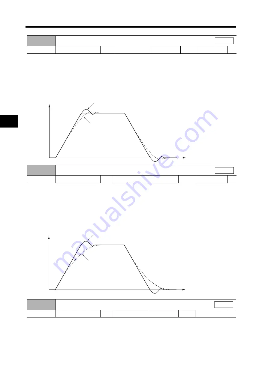
When the speed loop gain is changed, the response is as shown in the following diagram.
Set the speed loop integration time constant.
The higher the setting, the lower the responsiveness and the lower the resiliency to external force.
If the setting is too low, it causes oscillation.
This parameter is automatically changed by executing realtime autotuning function. To set it
manually, set the Realtime Autotuning Mode Selection (Pn21) to 0.
When the speed loop integration time constant is changed, the response is as shown in the
following diagram.
The encoder signal is converted to the speed signal via the low pass filter.
The higher the setting, the higher the time constant and the lower the noise level generated by the
Servomotor. Normally, use a setting of 4 or less.
This parameter is automatically changed by executing realtime autotuning function. To set it
manually, set the Realtime Autotuning Mode Selection (Pn21) to 0.
Pn11
Speed Loop Gain
Setting range
1 to 3500
Unit
Hz
Default setting
60
Power OFF
→
ON
---
All modes
Overshoots when the speed loop gain is
high. (Oscillates when the gain is too high.)
Servomotor
speed
When the speed loop gain is low.
Time
Pn12
Speed Loop Integration Time Constant
Setting range
1 to 1000
Unit
ms
Default setting
20
Power OFF
→
ON
---
All modes
Pn13
Speed Feedback Filter Time Constant
Setting range
1 to 5
Unit
---
Default setting
0
Power OFF
→
ON
---
Time
Overshoots when the speed loop integration time constant
is small.
When the speed loop integration
time constant is large.
Servomotor
speed
All modes


