background image

APPLIED OPERATIONS

/Protocol processor

OPERATION INSTRUCTIONS

2 - 1 8 7

Page

2-4-8-2 Example of Setting Procedure of XYT Observation for hours (Protocol using repetition
processing)

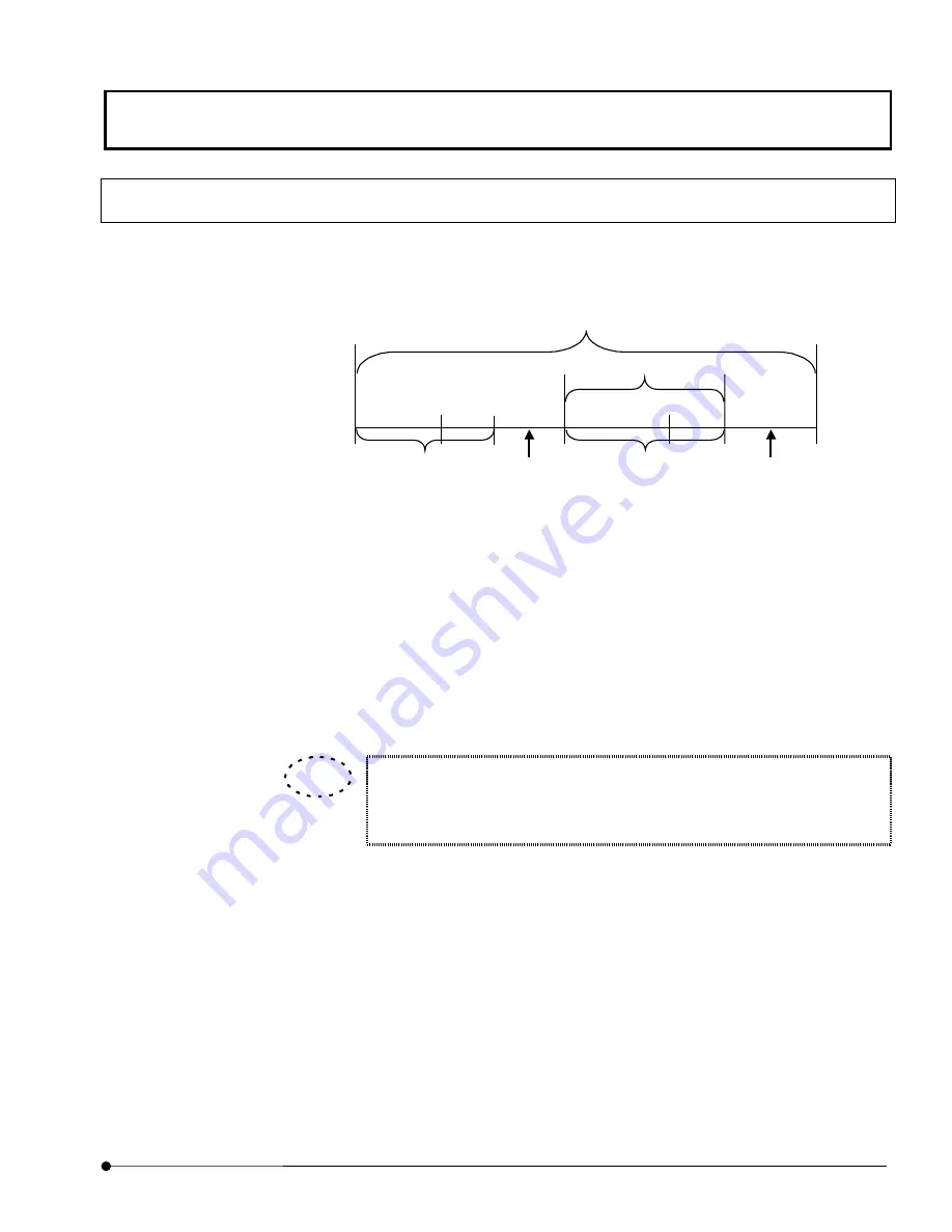
An example of editing a protocol using the repetition processing is described below

assuming the XYT observation including the GFP recovery observation for hours.

Acquisition of

9 images

Wait for 1 hour &

acquisition 9

 images

Protocol

Track 1

Save

Save

Track 3

Start of

repetition

Track 2

End of repetition

(Turnover)

Track 4

7 repeats

Reference image acquisition: Acquire 9 images with the zoom power 2 x, then save the

images acquired in Track 1.

Repeated Protocol start : Repeats protocol of Track 3, the repeated times is 7 which is

assigned with For statement in Track 2.

Long interval image acquisition:    Acquire 9 images every one hour, and the image is stored

in Track 3.

Repeated Protocol end: Track 4 defines whether ends or continues Track 3 protocol.

Specify the Z range and select XYZT mode before starting the XYZT

observation. For details, see section 2-2-1-4, “Setting the Observation

Condition”.

TIP

Summary of Contents for Fluoview FV1000

Page 1: ...ly before operation This user s manual is composed of two volumes including OPERATION INSTRUCTIONS and MAINTENANCE Together with this manual please also read the SAFETY GUIDE HARDWARE GUIDE of User s...

Page 2: ......

Page 3: ...hibited 2 The information described in this manual may be subject to change without notice Registered Trademarks Microsoft Microsoft Windows Excel for Windows are registered trademarks of Microsoft Co...

Page 4: ...1 1 2 APPLIED OPERATIONS 2 1 Appendix A List of Hot Keys A 1 Appendix B Glossary B 1 Appendix C USER REGISTRATION OF FV1000 C 1 Appendix D Change of Default Folder for File I O Panel D 1 Appendix E Li...

Page 5: ...alog box list box or check box is enclosed inside square brackets OK button Open File button The name of a button in a panel or dialog box is enclosed inside angled brackets Notation of Mouse Operatio...

Page 6: ...on keys Generic names given to the and keys Notation of system specific terms Notation Description XY observation Other observations Refers to observation with XY scanning The same principle also appl...

Page 7: ...when using a system notebook or file folder Function Window and Image Window The FLUOVIEW software is organized by two kinds of windows the function windows and the image window The function windows i...

Page 8: ...Analyze Single Saves loads and deletes images Changes the image display method Processes the acquired images Performs mathematical and logical operations between images Filters images Changes the imag...

Page 9: ...ing This software selects image files and observation methods dye name by means of dragging dropping This allows simple selection based on an intuitive operation of selecting an icon image file or obs...

Page 10: ...in the Files list box in the File I O panel or during dragging of an image file Use these icons to identify the observation methods used in image acquisition In all observation modes the icons for 3...

Page 11: ...ocedures of the FLUOVIEW FV1000 system Getting Started FLUOVIEW contains information on the basic operation flow until acquisition of XY images APPLIED OPERATIONS provides detailed operating procedure...

Page 12: ......

Page 13: ...scope IX81 FVF 1 18 1 2 4 Selecting the Dyeing Method 1 20 1 2 5 Selecting the Filters 1 23 1 2 6 Setting the ND Filters 1 26 1 2 7 Setting the Observation Condition 1 27 1 2 7 1 Setting the Objective...

Page 14: ...4 2 1 3 Examples of Operation Procedures 2 5 2 2 Image Acquisition 2 7 2 2 1 Image Acquisition in XY Observation Mode 2 8 2 2 1 1 Configuring the Microscope 2 9 2 2 1 2 Setting the Filters 2 15 2 2 1...

Page 15: ...ired Line XZ XT or XZT Observation 2 94 2 2 12 Image Acquisition in the Laser Excitation Mode 2 97 2 2 12 1 Making REX Mask File 2 98 2 2 12 2 Example of FRAP experiment 2 103 2 2 13 Notes for image a...

Page 16: ...a protocol 2 178 2 4 8 1 Example of Setting Procedure of FRAP Observation 2 178 2 4 8 2 Example of Setting Procedure of XYT Observation for hours Protocol using repetition processing 2 187 2 4 9 Pop u...

Page 17: ...rent Display Methods 2 218 2 5 7 6 Re arranging Images Using the Same Display Method 2 221 2 5 7 7 Displaying Different Images Together 2 221 2 5 8 Magnifying Reducing an Image 2 224 2 6 Image Process...

Page 18: ...Length Measurement 2 286 2 7 3 2 Area Measurement 2 286 2 7 3 3 Measuring the Change in Mean Value of Intensity 2 287 2 7 3 4 Measuring the Change in Integrated Intensity 2 293 2 8 Building an Image f...

Page 19: ...e of the Image 2 327 2 12 4 Drawing a Figure in Image 2 328 2 12 5 Drawing a Scale in Image 2 329 2 12 6 Drawing an Arrow in Image 2 330 2 12 7 Drawing Color Bars in Image 2 331 2 12 8 Deleting Commen...

Page 20: ...Dialog Box E 1 Appendix E 1 Coordinate Position Data E 1 Appendix E 1 1 X Coordinate E 1 Appendix E 1 2 Y Coordinate E 2 Appendix E 1 3 Other E 3 1 Z Position E 3 2 T Position E 3 3 Animation E 3 App...

Page 21: ...dix F 1 Hand Switch Functions F 1 Appendix F 1 1 BX BXWI F 1 Appendix F 1 2 IX F 2 Appendix F 2 Microscope Frame Functions F 3 Appendix F 2 1 BX F 3 Appendix F 2 2 IX F 4 Appendix F 2 3 Focus Adjustme...

Page 22: ......

Page 23: ...pment may differ from those shown below For detailed microscope operation procedures refer to the instruction manuals of your microscope Combination with BX61 2 Cube turret Cube display window This fi...

Page 24: ...page tab 1 Set cube turret in the state that mirror cube is entered 3 Analyzer IX2 MDICT Polarizing plate for use in differential interference observation and polarized light observation Rotate the t...

Page 25: ...FR Frost into the light path Disengaging the FR Frost from the light path may generate interference fringes on an image 6 Universal condenser Condenser for transmitted lighting In addition the rotary...

Page 26: ...TIONS 1 4 Page Combination with IX81 FVF 4 Transmitted light DIC slider U DICTS optional 1 Fluorescence mirror unit 2 Analyzer IX MDICT Optionally installed 5 Filters 4 Condenser 6 Hand switch U HSTR2...

Page 27: ...ation or transmitted polarized light observation 3 Transmitted light DIC slider U DICTS This is a prism for use in differential interference observation Engage U DICTS in the light path for laser diff...

Page 28: ...bservation or laser differential interference observation engage the polarizing plate in the light path 5 Filters These filters are used to adjust transmitted light For transmitted observation using l...

Page 29: ...t something and execute its function Double clicking To double click place the mouse pointer on the desired function and press the mouse button successively twice To move something Dragging To drag pl...

Page 30: ...ox groups functions with specific meanings and encloses them in a frame List box Shows the list of available items for selection All items in the list can be displayed by scrolling To select an item i...

Page 31: ...combiner is used set the optimum ND filters for the laser Section 1 2 6 z Let an appropriate cube for dyeing method into the light path z Select the light path for 100 binocular tube and focus on the...

Page 32: ...or the laser Section 1 2 6 Set the objective magnification Section 1 2 7 1 Set the zoom ratio to 1X Section 1 2 7 2 Set the channels Section 1 2 7 3 Set the highest scan speed Section 1 2 7 4 Select t...

Page 33: ...UCTIONS 1 1 1 Page 1 2 1 Turning Power On Set the power switch of each unit to ON then start the software For details see sections 1 1 Turning the Power On and section 1 2 Starting the Software in Vol...

Page 34: ...ttings Sub panel 3 Select the BI button in the Light Path group box The BI button looks pushed in to indicate that it is selected 4 Push the cube button 5 of the hand switch 4 to engage the optimum cu...

Page 35: ...ecimen may float during oil immersed observation In this case prepare an optional clip for immersion objective and attach it as shown on the left If you want to use a differential interference unit in...

Page 36: ...BI button looks pushed in to indicate that it is selected Fig 1 4 Settings Sub panel 2 Engage the optimum cube for specimen dye by pressing the cube turret 2 when using Manual microscope Engage the o...

Page 37: ...ndle of microscope or U FH uncheck checkbox of Locked on Z Stage sub panel inside Acquire panel See 2 2 1 4 7 of this manual When Locked checkbox is checked the handle cannot be operated The specimen...

Page 38: ...ig 1 5 Settings Sub panel 2 Select the LSM button in the Light Path group box The LSM button looks pushed in to indicate that it is selected When scanning is started while the BI button is selected th...

Page 39: ...transmitted light DIC for the objective in the light path by operating the universal condenser 5 5 For transmitted light observation disengage any filter 4 from the light path When you perform transmi...

Page 40: ...scanning completes 2 Push the hand switch button 7 to set reflected light fluorescence mirror unit to 1 3 When a fluorescence observation alone is required disengage the U DICTS transmitted DIC slide...

Page 41: ...TIONS 1 1 9 Page 4 During the transmitted light observation be sure to disengage the filter 5 from the light path 1 Fluorescence mirror unit 2 Analyzer IX MDICT Optionally installed 3 Transmitted DIC...

Page 42: ...of the Acquire panel Available Dyes list box Lists the available dyes Select the desired items from this list and drag them to the field above it to select the dyeing method Clear button Clear the set...

Page 43: ...ding to the switched filter And the dyeing method is shown in the Ch group box The Confocal Aperture value is also set automatically according to the wavelength and the objective for every channel If...

Page 44: ...Assign dyes manually check box in the Dyes sub panel 2 Select the dyeing method in the Available Dyes list box and drag it directly to the field of the Ch check box 3 After dragging the icon appears...

Page 45: ...SDM510 5 6 1 Mirror 2 Glass 3 SDM640 4 5 6 1 BA505IF 2 BA505 525 3 BA480 495 4 5 6 1 BA560IF 2 BA560 620 3 BA535 565 4 5 6 1 BA650IF 2 3 4 5 6 Multiline Ar HeNe G HeNe R 458 488 515 543 633 3 channels...

Page 46: ...SDM490 6 1 Mirror 2 Glass 3 SDM640 4 SDM560 5 6 1 BA465 495 2 BA505 525 3 BA430 470 4 BA480 495 5 6 1 BA505IF 2 BA560 620 3 BA535 565 4 BA505 525 5 6 1 BA650IF 2 BA560IF 3 4 5 6 LD405 Multiline Ar Kr...

Page 47: ...550 5 6 1 BA650IF 2 BA585IF 3 4 5 6 UV Multiline Ar HeNe G HeNe R 351 458 488 515 543 633 4 channels 1 BS20 80 2 DM351 488 3 DM488 543 633 4 DM351 543 5 DM458 515 6 1 Mirror 2 Glass 3 SDM490 4 SDM510...

Page 48: ...Laser Intensity group box of the Lasers sub panel in accordance with specimen s brightness fluorescence crosstalk and photo bleaching Fig 1 7 Lasers Sub panel While using the HeNe green laser try out...

Page 49: ...etting the Objective Magnification From the drop down list on the center of the Acquire panel select the objective being used with the microscope If you change the objective click the Apply button in...

Page 50: ...he Ch group box make sure that the check boxes showing the applicable dyeing methods are check marked to indicate that the channels are ready for image acquisition If the check box of a channel is not...

Page 51: ...can sub panel Select either option button in the Focus Mode group box The focus mode is enabled when acquiring images using the Focus button The Focus function reduces the scanning time by line skippe...

Page 52: ...observation mode option button 1 2 7 6 Repeated Scanning Operation 1 Select the XY Repeat button The acquired image will be displayed in the Live panel Use the FOCUS button to acquire image at an eve...

Page 53: ...n the fine focus adjustment knob while the Locked check box is checked for this may damage the Z motor 3 While observing the image in the Live panel locate the plane to be observed by displacing the s...

Page 54: ...an speed is decreased during fluorescence observation the saturation of fluorescence may darken the image of certain types of specimens In this case increase the scan speed and increase the PMT Voltag...

Page 55: ...topping Repeated Scanning After the brightness and gain have been adjusted select the STOP SCAN button in the Acquire panel to stop scanning temporarily 1 2 8 Acquiring Image Select the Once button Th...

Page 56: ...it is possible to select whether images from more than one image are saved simultaneously or only one of the images is saved Use the Display channel switch buttons to select the images to be saved Th...

Page 57: ...og Box 4 Enter the file name in the File name text box 5 Select FLUOVIEW MultiTif from Save as type 6 Click the Save button 1 2 10 Exiting from the Software Turning Power Off Exit from the software th...

Page 58: ...a simple method for displaying and consulting the online help on the functions and operation procedures The figure below shows the initial display table of contents of the FLUOVIEW Online Help window...

Page 59: ...specimen dyeing method by dragging desired dye names in the Available Dyes list box in the Selected Dyes group box to the field immediately above the list box TIP Available Dyes list box Lists the ava...

Page 60: ...he Acquire panel When the dyeing method is selected from the Available Dyes list box and the Apply button is clicked a channel for acquiring fluorescence is set automatically according to the changed...

Page 61: ...manually check box in the Dyes sub panel 2 Select the dyeing method in the Available Dyes list box and drag it directly to the field of the Ch check box 3 After dragging the icon appears on the right...

Page 62: ...tion with BX61 or IX81 is in use the microscope and scan unit can be configured on the FLUOVIEW software Use the following procedure to configure the microscope 1 From the panel page tabs shown on the...

Page 63: ...light path The top lens is engaged into the light oath The top lens is disengaged from the light path Condenser Turret group box Clicking the universal condenser automaticallyswitches the turret Aper...

Page 64: ...automatically switches the turret Shutter group box Clicking inside the box switches the EPI shutter to be closed opened The shutter is opened The shutter is closed EPI lamp Indicates the EPI lamp La...

Page 65: ...ece group box BX only Checking here closes the shutter when the Mirror Units are switched in the Mirror Unit Checking here sets the TD lamp to OFF when the fluorescent cube is selected in the Mirror U...

Page 66: ...be applied Selecting the Import Setting button of the Link Setting dialog box displays the Open dialog box as shown below When the setting file which you want to read is not displayed in the list box...

Page 67: ...change the save destination drive or directory use the Save in drop down list Enter the setting file name into the File name text box Select the Save button to close the dialog box z The Focus Settin...

Page 68: ...begin the parfocality correction from the value of the objective with maximum magnification in descending order click the Next button in the Pfcl Setup Wizard group box Objectives group box Click the...

Page 69: ...the parfocality correction value setting with the objective with the maximum magnification click the Switch to option button then click the Next button Click to set the objective with the maximum magn...

Page 70: ...4 8 Page 5 The objective set as the specified in the Objectives group box is selected and the Pfcl Setup Wizard group box displays the message shown below Bring the specimen in focus by observing it v...

Page 71: ...ext button Click to proceed to the setting of the objective with next higher power to the current objective Click to select the desired objective from the Objectives group box and set the parfocality...

Page 72: ...urrent focal position as the parfocality correction value for the current objective and proceed to the setting of the next objective Click to set the parfocality correction value of the current object...

Page 73: ...e in the Jog Fine 10 After completing the setting click the Save each Perfocal value and Jog Setting then Exit option button and then click the Next button The setting will be registered and the dialo...

Page 74: ...ilter and beam splitter are set automatically to the light path according to the dyeing method selected for the specimen Use the following procedure to change these filters 1 Select the Settings sub p...

Page 75: ...o suppress useless electric power consumption we recommend you making Stby mode The laser oscillation stops when the time shown in this box has elapsed after the end of laser scanning The laser oscill...

Page 76: ...YPSF NA XYPSF 5 1459x6 1 0147 10x5 7 1668x4 2 2804x3 1 7696 10 1 x2 1 9256 10 02 x 7 1915 10 1 The case where the variable x is as follows 0 5 x 1 0 FWHM 0 5 XYPSF NA XYPSF 3 05539x6 1 32031 10x5 2 25...

Page 77: ...NA nSIN NA of Objective lens MG The objective Magnification N The refractive index of a medium Air 1 0 Water 1 3 Oil 1 5 X L 1 22 3 8 MG NA The case where the variable x is as follows 0 x 2 0 FWHM 2...

Page 78: ...y desired wavelength regions can be selected easily To acquire image with a spectral detecting system set the wavelength regions in the Spectral Control sub panel Fig 1 18 Spectral Control sub panel a...

Page 79: ...e bottom of the Settings sub panel When the window shown below is displayed set up the spectral detecting system in the SPD group box Fig 1 20 Optical System Configuration window Scan Unit button Disp...

Page 80: ...ION INSTRUCTIONS 1 5 8 Page For other functions available in the Optical System Configuration window see section 1 3 2 3 Configuring the Filters When using a filter system 3 After completing the setup...

Page 81: ...omatically according to the selected dyeing method Use the following procedure to change the pinhole diameters 1 Display the Acquire panel Ch group box Sets whether the image of each channel is to be...

Page 82: ...PMT Gain and Offset LED sliders Set these values independently Increasing the PMT Voltage improves the sensitivity Increasing the Gain brightens the image Increasing the Offset darkens the image Ch1 C...

Page 83: ...lues independently Increasing the PMT Voltage improves the sensitivity Increasing the Gain brightens the image Increasing the Offset darkens the image Ch1 Ch2 Ch3 Ch4 and Ch5 group boxes Select the ch...

Page 84: ...r ND LED slider increases or decreases the laser ND value by 1 Each click of the slider section of the Laser ND LED slider varies the laser ND value by 5 To set to the Confocal Aperture value to its p...

Page 85: ...to get accustomed with the operation Begin using the FLUOVIEW system by acquiring an image or opening an image from a file For the detailed operation method of each item in the procedure see the sect...

Page 86: ...nimation display Section 2 9 2 Continuous display Frame by frame display Section 2 9 1 z Observation of image change over time Side by side image display Section 2 10 1 Continuous display Frame by fra...

Page 87: ...provides the following observation modes Configure the system and confirm the images to be observed The system configuration and image confirmation are described in details in section 1 2 Outline of...

Page 88: ...n 2 2 2 Image Acquisition in Other Observation Modes as well as the following procedure Set the acquisition parameters Section 2 2 1 4 z Observation mode z Scanning speed z Image brightness Acquire an...

Page 89: ...asure the intensity distribution and edit data with Excel Specify the area to be measured Measure the intensity distribution Section 2 7 2 Exit from the FLUOVIEW software and turn power OFF Sections 1...

Page 90: ...xit from the FLUOVIEW software and turn power OFF Sections 1 2 10 Output the image at the printer Section 2 13 Open an image in a file Section 2 3 2 Exit from the FLUOVIEW software and turn power OFF...

Page 91: ...ition Confirm the image to be acquired using the microscope and acquire its image using FLUOVIEW The image can be saved in a file as required If FLUOVIEW window is moved while an image is being acquir...

Page 92: ...OPERATION Set the channel to be acquired Section 2 2 1 4 3 in OPERATION Set the highest scan speed Section 2 2 1 4 4 in OPERATION Perform repeated scanning Section 2 2 1 4 6 in OPERATION Set the XY o...

Page 93: ...ng to display images successively in the Live panel Option buttons Check a button to select one of the displayed observation modes Scan Speed group box Sets the scan speed Sliding to the left of the s...

Page 94: ...e dyes Select the desired items from this list and drag them to the field above it to select the dyeing method Clear button Clear the set dyeing method Prev button Sets the dyeing method which was set...

Page 95: ...el for acquiring fluorescence is set automatically according to the changed filter And the dyeing method is shown in the Ch group box The Confocal Aperture value is also set automatically according to...

Page 96: ...manually check box in the Dyes sub panel 2 Select the dyeing method in the Available Dyes list box and drag it directly to the field of the Ch check box 3 After dragging the icon appears on the right...

Page 97: ...sition OPERATION INSTRUCTIONS 2 1 3 Page 3 From the panel page tabs shown on the bottom right of the Acquire panel select the Optics sub panel Fig 2 4 Optics Sub panel Scope button Displays useful inf...

Page 98: ...on with the IX81 Fig 2 5 Microscope Control Panel Window 5 Configure the microscope in Microscope Control Panel window 6 After completing the setup click the Close button to close the window For detai...

Page 99: ...light path according to the dyeing method selected for the specimen To change filters use the following procedure 1 From the panel page tabs shown on the bottom right of the Acquire panel select the...

Page 100: ...group box Shows the type of laser to be used With the laser combiner operation the laser type is set and displayed automatically When the On button is pressed in the laser is oscillating the beam When...

Page 101: ...Laser Intensity group box of the Lasers sub panel in accordance with specimen s brightness fluorescence crosstalk and photo bleaching While using the HeNe green laser try out the laser power 50 by se...

Page 102: ...ND value using the Laser LED slider Each click of the laser ND or varies the laser ND value by 1 Each click of the laser ND slider varies the laser ND value by 5 Clicking this field allows the ND valu...

Page 103: ...tive magnification set here does not match the actual magnification of the objective in use If you change the objective click the Apply button in the Dyes sub panel The Conforcal Aperture value is set...

Page 104: ...od to ready the image acquisition 3 In the Channel 3 group box check the check box showing the applicable dyeing method to ready the image acquisition 4 In the Channel 4 group box check the check box...

Page 105: ...elect either option button in the Focus Mode group box The focus mode is enabled when acquiring images using the Focus button The Focus function reduces the scanning time by line skipped scan As a res...

Page 106: ...eat button The Focus function reduces the scanning time by line skipped scan As a result the acquired images become coarse 7 Setting the Multiple sections to be Observed While acquiring image move the...

Page 107: ...ons can be changed See section 1 3 in MAINTENANCE Setting the System Configuration for detailed operations 1 Check the Locked check box in the Z Stage sub panel 2 While observing the image in the Live...

Page 108: ...o the left of the Zoom scale represents the field visible through the microscope and the blue frame indicates the acquired image area Move the blue frame inside the circle using the Pan buttons so tha...

Page 109: ...quisition This value can be set independently from the Offset For example When the acquired image is dark or the observation targets are hardly visible increase PMT voltage to improve the sensitivity...

Page 110: ...Each click of the or button of the Gain LED slider increases or decreases the Gain by X0 1 Each click of the slider section of the Gain LED slider varies the Gain by X1 0 Each click of the or button o...

Page 111: ...ses in the image different colors may appear in its background When the intensity is saturated the portion will be colored with Red Based on this coloring you may adjust the image intensity Hi Lo LUT...

Page 112: ...is decreased during fluorescence observation the saturation of fluorescence may darken the image of certain types of specimens In this case increase the scan speed and increase the PMT Voltage or use...

Page 113: ...ps image acquisition when any intensity value on the image reaches the peak 4095 This operation is effective for acquiring an image with the dark lower part in the XYZ observation and observation of a...

Page 114: ...x select the Kalman or Accumulate option button 3 When Kalman is selected enter the accumulation count in the text box And select the Frame button displayed The accumulation count can be set up a maxi...

Page 115: ...quiring Image in Accumulation Mode Line mode Image acquisition in the line mode can be performed when you use the FV1000 system with AOTF FV5 COMBA 1 From the page tabs on the bottom right of the Acqu...

Page 116: ...Live panel And the accumulated image can be displayed in the image window without being displayed in full The difference between the Frame and Line modes of Kalman Accumulation In frame mode the imag...

Page 117: ...red Image in File 1 Display the File I O panel 2 Click the page tab of the Live panel showing the image to be saved so that the image is displayed at the front 3 Click the Experiment button in the Sav...

Page 118: ...ghest scan speed Section 2 2 1 4 4 in OPERATION Perform repeated scanning Section 2 2 1 4 6 in OPERATION Set the XY observation mode Section 2 2 1 4 5 in OPERATION Set the observation range Section 2...

Page 119: ...sition in the range of the observed cross section Z direction scanning range Start Z text box Shows the scan start position in the range of the observed cross section Z direction scanning range Set bu...

Page 120: ...ple sections to be observed Z direction scanning range 4 While observing the image in the Live panel locate the bottom edge of the range to be observed by moving up the stage using the Z stage coarse...

Page 121: ...The number of steps in the Step Size text box has been calculated by the system so that the depth scale of the acquired image is identical to the horizontal scale The number of steps calculated by th...

Page 122: ...be acquired Section 2 2 1 4 3 in OPERATION Set the highest scan speed Section 2 2 1 4 4 in OPERATION Perform repeated scanning Section 2 2 1 4 6 in OPERATION Set the XY observation mode Section 2 2 1...

Page 123: ...ve 3 Setting the number of scans 1 Set the number of scans using the or button in the N text box in the Time Series sub panel 4 Acquiring image 1 Click the XT button in the Acquire panel The acquired...

Page 124: ...ERATION Re adjust the image brightness Section 2 2 1 4 9 in OPERATION Stop repeated scanning Section 2 2 1 4 11 in OPERATION Set the observation mode Section 2 2 2 3 2 in OPERATION Acquire image Secti...

Page 125: ...observed cross section Z direction scanning range Start Z text box Shows the scan start position in the range of the observed cross section Z direction scanning range Set button Sets the current stage...

Page 126: ...of the range of the multiple sections to be observed Z direction scanning range 4 While observing the image in the Live panel locate the bottom edge of the range to be observed by moving up the stage...

Page 127: ...ing the or button in the Step Size text box The number of steps shown in the Step Size text box has been calculated by the system so that the depth scale of the acquired image is identical to the hori...

Page 128: ...so sets the Interval text box to Free Run 6 Setting the number of scans 2 Set the number of scans using the or button in the N text box in the Time Series sub panel Rest Time text box Shows the time a...

Page 129: ...he XZT observation mode the buttons at the upper part of the Acquire panel changes as shown below Click the Append Next button to append an image An image will be acquired with the same number of step...

Page 130: ...the highest scan speed Section 2 2 1 4 4 in OPERATION Perform repeated scanning Section 2 2 1 4 6 in OPERATION Set the XY observation mode Section 2 2 1 4 5 in OPERATION Set the observation range Sec...

Page 131: ...observed cross section Z direction scanning range Start Z text box Shows the scan start position in the range of the observed cross section Z direction scanning range Set button Sets the current stage...

Page 132: ...n is located click the Set button The Start Z text box will show the scan start position of the range of the multiple sections to be observed Z direction scanning range 4 While observing the image in...

Page 133: ...Size number of steps 3 Setting the observation mode 1 In the Mode group box in the Acquire panel select the Surface option button 2 In the Acquire panel select the XYZ observation mode option button...

Page 134: ...s as shown below Click the Append Next button to append an image An image will be acquired with the same number of steps as the image acquired immediately before and appended to it Click the Series Do...

Page 135: ...n 2 2 1 4 3 in OPERATION Set the highest scan speed Section 2 2 1 4 4 in OPERATION Perform repeated scanning Section 2 2 1 4 6 in OPERATION Set the XY observation mode Section 2 2 1 4 5 in OPERATION S...

Page 136: ...nterval text box An image with no interval can be acquired by entering 0 in the Interval text box In this case the Interval text box shows Free Run message Using button also sets the Interval text box...

Page 137: ...y heat causing the focusing to be deviated To acquire precise image data it is recommended to set the power switch of the transmitted light illumination to O OFF While acquiring an image in the XYT ob...

Page 138: ...s as shown below Click the Append Next button to append an image An image will be acquired with the same number of steps as the image acquired immediately before and appended to it Click the Series Do...

Page 139: ...Set the highest scan speed Section 2 2 1 4 4 in OPERATION Perform repeated scanning Section 2 2 1 4 6 in OPERATION Set the XY observation mode Section 2 2 1 4 5 in OPERATION Set the observation range...

Page 140: ...observed cross section Z direction scanning range Start Z text box Shows the scan start position in the range of the observed cross section Z direction scanning range Set button Sets the current stage...

Page 141: ...n is located click the Set button The Start Z text box will show the scan start position of the range of the multiple sections to be observed Z direction scanning range 4 While observing the image in...

Page 142: ...e observation mode 1 In the Mode group box in the Acquire panel select the Surface option button 2 In the Acquire panel select the XYZT observation mode option button 4 Setting the interval time 1 Fro...

Page 143: ...hen the built in power supply for transmitted light illumination is used for a long period in the XYZT mode the metallic parts may be expanded by heat causing the focusing to be deviated To acquire pr...

Page 144: ...es as shown below Click the Append Next button to append an image An image will be acquired with the same number of steps as the image acquired immediately before and appended to it Click the Series D...

Page 145: ...ethod to the Ch group box on the upper part of the Acquire panel When the dyeing method is selected from the Available Dyes list box and the Apply button is clicked a channel for acquiring fluorescenc...

Page 146: ...manually check box in the Dyes sub panel 2 Select the dyeing method in the Available Dyes list box and drag it directly to the field of the Ch check box 3 After dragging the icon appears on the right...

Page 147: ...Make the channel ready for image acquisition In the Acquire panel make sure that the check box in the Ch1 Ch2 Ch3 Ch4 group box that shows the dyeing method is check marked to indicate that the corre...

Page 148: ...part of the Acquire panel When the dyeing method is selected from the Available Dyes list box and the Apply button is clicked a channel for acquiring fluorescence is set automatically according to th...

Page 149: ...manually check box in the Dyes sub panel 2 Select the dyeing method in the Available Dyes list box and drag it directly to the field of the Ch check box 3 After dragging the icon appears on the right...

Page 150: ...isition In the Acquire panel make sure that the check box in the Ch1 Ch2 Ch3 Ch4 group boxes that show the dyeing methods are check marked to indicate that the corresponding channels are ready for ima...

Page 151: ...e dyeing method is selected from the Available Dyes list box and the Apply button is clicked a channel for acquiring fluorescence is set automatically according to the changed filter And the dyeing me...

Page 152: ...manually check box in the Dyes sub panel 2 Select the dyeing method in the Available Dyes list box and drag it directly to the field of the Ch check box 3 After dragging the icon appears on the right...

Page 153: ...itted light bulb of the microscope 1 From the page tabs on the bottom right of the Acquire panel select the Settings sub panel Fig 2 23 Settings Sub panel 2 Click the Tr Lamp button to turn the lamp o...

Page 154: ...Please use PMT Offset and Gain LED sliders in Ch5 group box to adjust the brightness of the transmitted image For details see section 2 2 1 4 9 Adjusting the Image Brightness in the OPERATION volume...

Page 155: ...lip Scan 2 2 6 Image Acquisition by Magnifying the Rectangular Position Zoom In Scan 2 2 7 High Speed Image Acquisition and 2 2 8 Acquiring Finer Image Sequential Scan 3 Specify the image rotation ang...

Page 156: ...rea is limited to an area with 400 x 300 pixels halved in both X and Y directions When the image is acquired in this mode the size per pixel on the specimen is identical to that before start of this m...

Page 157: ...er on an inclining position and click the mouse left button to fix the frame inclination angle 7 When using hardware that is compatible with rotation scan FV5 IO3 specify the image rotation angle usin...

Page 158: ...box to set the scanning range to the original setting It is not permitted to change the scanning range after having acquired images If you want to change the scanning range again select Normal from th...

Page 159: ...of this mode and the magnification applied is determined according to the size of the limited range High speed image acquisition can be made possible by decreasing the number of pixels in the Y direc...

Page 160: ...in it to display square handles around the frame Place the mouse pointer on one of these handles and drag it to change the number of pixels Note that the X Y ratio of the frame is not changed during t...

Page 161: ...ct Normal under the Surface XY option button in the Mode group box in the Acquire panel to return from the image acquisition mode Dragging the blue handle along the circuit allows the acquisition area...

Page 162: ...roup box in the Acquire panel Then select Fast in the list shown below 512 by 512 is set automatically in the Size drop down list in the Mode group box X2 is set and shown in gray out display automati...

Page 163: ...rface XY Note option button in the Mode group box in the Acquire panel then select Sequen in the list shown below Selecting Sq Clp Sq Rct or Line Sq enables the image acquisition of the desired rectan...

Page 164: ...sition starts with the smallest group number set To prevent unwanted color fading it is recommended to acquire the image from the reagents with longer wavelengths 5 Click the Seq Once button to acquir...

Page 165: ...the Rdy button displayed in the pressed in condition 8 Click the OK button in the FLUOVIEW dialog box Image acquisition starts 9 Adjust the brightness with the PMT Offset and Gain LED sliders in the...

Page 166: ...number of detection channels Up to 6 virtual channels can be set up If 6 channels are already used by means of option units it is no longer possible to set up a virtual channel Operation Example The f...

Page 167: ...ire panel because the virtual channels are not compatible with Line Sequential Scan If the observation mode is set to Sequential Scan the Dyes sub panel in the Acquire panel cannot be used 4 Using the...

Page 168: ...p up menus It is not permitted to set the physically identical channels an ordinary channel and virtual channel in the same group For example ordinary channel 1 and virtual channel 1 cannot be set in...

Page 169: ...select Glass In the Barrier Filter drop down list for CH2 select BA660IF In the Laser Unit group box click the picture of shutter and engage the HeNe R laser in the light path After completing the set...

Page 170: ...last is applied to all groups When the laser to be used with a group has not been set the Laser Unit dialog box shows No Laser has assigned yet In this case set the laser in the Laser Unit group box...

Page 171: ...ng the image brightness 10 Click the STOP SCAN button to stop repeated scanning 11 Repeat steps 7 and 10 for each of the groups to be configured 12 Click the Seq Once button to start sequential scan 1...

Page 172: ...panel A line indicating the control range appears in the Live panel 3 Move the line to the area to be observed To move the line place the mouse pointer on it and drag the mouse 4 Change the line lengt...

Page 173: ...ng the laser to certain point on the image If you have FLUOVIEW TIME COURSE software image acquisition can be started with buttons keys or input of external trigger signals 1 Acquire an image in the X...

Page 174: ...values appears in the Live panel 3 Move the cross cursor to the area you want to observe To move the cross cursor place the mouse pointer on it and drag the mouse 4 Set the scan speed for image acquis...

Page 175: ...t of the Acuire panel select the Time Series sub panel Set the time for measurement with the or button in the Scanning text box 6 Set the starting method for image acquisition If you have FLUOVIEW TIM...

Page 176: ...direction specified in the Live panel When a certain area is specified by dragging the mouse from the top left to the bottom right on the graph while pressing down its left button the specified area...

Page 177: ...e X or Y Axis on the graph window the Editing dialog box appears and the graph parameters or the graph display method can be modified 9 After image acquisition select Normal under the Surface XY optio...

Page 178: ...d operation see section 2 2 1 Image Acquisition with XY observation 2 Select Line XT option button in the Mode group box in the Acquire panel or Free under the Depth XZ option button A line indicating...

Page 179: ...the handle The handle can be added by clicking the mouse on desired coordinates To delete the handle right click the mouse on it Right click the mouse on the coordinates but the handles to fix the sha...

Page 180: ...ext box in the Time Series sub panel 7 Click XZ XT or XZT etc to acquire the image The image shown in the Live panel after image acquisition is the image that acquired at the curved line specified on...

Page 181: ...itation in this section Three kinds of the laser excitation mode Disable REX and Bleach are selectable according to your purpose And each mode can be switched in the XYT observation In use of the REX...

Page 182: ...fast scan and image acquisition in the Line mode Normal Slant and Free can not be performed The specimen in the images carried in this section is not for FRAP but for the user s manual 2 2 12 1 Makin...

Page 183: ...lar Circle Polyregion or Free region button And drag on the image to specify the region of laser excitation In order to specify two or more regions click the mouse on or inside the region with holding...

Page 184: ...s sub panel Fig 2 26 Lasers sub panel When the Make REX mask button is displayed in gray click and select the specified region on the Live panel When two or more regions are specified select all the r...

Page 185: ...the REX Live panel has already been created on the software A panel is continuously created after REX_Live0 The REX mask file can be saved The saving procedure is completely the same as that of a dis...

Page 186: ...becomes brighter as the value is close to 100 In case of using REX function setting of Laser Intensity in Laser sub panel is recommended to set 100 Otherwise the actual laser intensity may not be rep...

Page 187: ...t is because the square power of zoom magnification per time can be secured Moreover using the objective of larger NA concentrates the laser irradiation spot in Z direction and stronger laser can be i...

Page 188: ...example after acquiring an image 3 Making REX Mask File See section 2 2 12 1 Making REX Mask File for the procedure to make the REX mask file If the setup of the region of laser excitation remains aft...

Page 189: ...y the pop up menu as shown below Select the image to be masked in the menu In order to use the already saved file as a REX mask file open the image beforehand The opening method of the REX mask file i...

Page 190: ...EX mask file is completely the same as that of an image For details see section 2 3 2 Opening Previously Saved Images in this manual 6 The icon of the selected REX mask file is displayed inside the fr...

Page 191: ...Image Acquisition OPERATION INSTRUCTIONS 2 1 0 7 Page 5 Setting the XYT Observation mode 1 Confirm that XY Norm is displayed in the Mode group box in the Acquire panel 2 Select the XYT option button i...

Page 192: ...he Total Time text box The time for image acquisition differs according to the interval and the number of scans 6 Setting the TIME COURSE Software optional Setting of the real time graph is required w...

Page 193: ...the REX mode is effective to prevent fading of the obtained data 1 Select the Disabled option button in the AOTF group box in the Lasers sub panel 2 Click the XYT button to start image acquisition 3...

Page 194: ...Select the the Disabled or REX mode option button within 10 seconds before the next scanning is started In the TIME COURSE software optional when the REX mask file in the REX or Bleach mode is changed...

Page 195: ...ecimen is acquired When performing the forth or subsequent scan be sure to switch the REX mode and Bleach mode between scans In the TIME COURSE software optional when the REX mask file in the REX or B...

Page 196: ...ion Setting ROI Region Of Interest This Scanning Region Setting ROI holds the setting information described below when scanning is executed and the information appears in the same state when each scan...

Page 197: ...ects the type of the files to be displayed in the Files list box Directory list box Shows the hierarchical list of disks and directories Double click the required disk and directory If the required di...

Page 198: ...e also displayed in the Icon field in the Files list box In all observation modes the icons for 3 or more channels are identical Image Icon Significance XZ observation XZ observation 2 channel mode Xt...

Page 199: ...acquired in the Z direction Icon Icons showing the image observation modes Y Image sizes in the Y direction X Image sizes in the X direction T Number of images acquired over time Ch Number of image ch...

Page 200: ...sition button Also set the save end position in the similar way 3 When the images to be saved are acquired from more than one channel select whether saving images from more than one channel simultaneo...

Page 201: ...n 1 2 2 8 File I O Panel in FV300 500 1000 Newly Added Functions 8 Click the Save button If a file with the same name as the entered file name already exists a dialog box is displayed to ask if you wa...

Page 202: ...application 1 Display the image window showing the image to be saved at the front 2 When there is more than one image to be saved display the image to be saved using the Display buttons 3 Click the D...

Page 203: ...list See section 2 3 1 4 File Types Available for Save for details 6 Enter the file name in the File Name text box 7 Click the Save button If a file with the same name as the entered file name alread...

Page 204: ...slices for multiple channels are saved together or the image slice of only 1 channel is saved Use the display switching button for the selection The image will be saved in the channel condition as di...

Page 205: ...ton so that the list of buttons disappear 7 Click the Experiment button in the Save group box The Save Experiment As dialog box appears Fig 2 31 Save Experiment As Dialog Box 8 Use the Save In drop do...

Page 206: ...2 Page 12 A dialog box as shown below appears Fig 2 32 Saving a subset of Experiment s Data Dialog Box The Saving a subset of Experiment s Data dialog box does not appear if no area is specified in t...

Page 207: ...ssive Display Speed One Point When saving image slices acquired in Z observation it is recommended to lower the animation display mode by clicking the Turtle button If image slices are saved with the...

Page 208: ...n it is required to change the saved file type use the Save as Type drop down list Two saving methods can be selected AVI compressed Saves the AVI file being compressed AVI Uncompressed Saves the AVI...

Page 209: ...ng etc on FLUOVIEW Single TIF s 8 bit tif Single TIF s 16 bit Gray Scale tif TIFF Tagged Image File Format is used for Single TIF s 24 bit tif image exchange between applications or computers Three ty...

Page 210: ...when the image will be analyzed or processed after save Opening the image also opens the comment which can be changed or measured as required Single TIF s Select when the image will be handed to anoth...

Page 211: ...aving a channel under displayed condition Side by side images and Merged images on the left The image is saved in the original non extended status To be saved Single TIF s 8 bit 12 images obtained by...

Page 212: ...tif Ch1 No 3 abcdefgh4 tif Ch2 No 0 abcdefgh7 tif Ch2 No 3 abcdefgh8 tif Ch3 No 0 abcdefgh11 tif Ch3 No 3 4 images are saved only from Ch3 Save file names abcdefgh0 tif Ch3 No 0 abcdefgh3 tif Ch3 No...

Page 213: ...0 abcdefgh3 tif Ch3 No 3 4 images are saved from each of Ch1 Ch2 and Ch3 Save file names abcdefgh0V0 tif Ch1 No 0 abcdefgh0V3 tif Ch1 No 1 abcdefgh0V6 tif Ch1 No 2 abcdefgh0V9 tif Ch1 No 3 abcdefgh1V1...

Page 214: ...bcdefgh0 bmp Ch1 No 0 abcdefgh3 bmp Ch1 No 3 abcdefgh4 bmp Ch2 No 0 abcdefgh7 bmp Ch2 No 3 abcdefgh8 bmp Ch3 No 0 abcdefgh11 bmp Ch3 No 3 4 images are saved only from Ch3 Save file names abcdefgh0 bmp...

Page 215: ...cdefgh3 bmp Ch3 No 3 4 images are saved from each of Ch1 Ch2 and Ch3 Save file names abcdefgh0V0 bmp Ch1 No 0 abcdefgh0V3 bmp Ch1 No 1 abcdefgh0V6 bmp Ch1 No 2 abcdefgh0V9 bmp Ch1 No 3 abcdefgh1V1 bmp...

Page 216: ...or directory to those containing the desired file using the Drive drop down list and or Directory list box 2 From the File Type drop down list select the file type of the files to be listed in the Fi...

Page 217: ...st button in the toolbar at the bottom of the File I O panel The Experiments in Memory dialog box appears as shown below Fig 2 34 Experiments in Memory Dialog Box 2 In the Experiments in Memory dialog...

Page 218: ...Memory dialog box while showing multiple images in the image window 2 Pressing down the Shift key select multiple image files to be shredded 3 Click the Shredder button 4 Click the Done button in the...

Page 219: ...in the toolbar at the bottom of the File I O panel The Experiments in Memory dialog box appears as shown below Fig 2 35 Experiments in Memory Dialog Box One Point Experiments in Memory dialog box move...

Page 220: ...nter comment from the keyboard During modification of previously entered commenbmp it is required to restore the originally entered comment click the Restore Comments button However once the Save Comm...

Page 221: ...File I O panel at the front 9 Click the Experiment button in the Save group box See section 2 3 1 Saving Images for details TIP One Point The Image Comments dialog box can also be displayed by a mous...

Page 222: ...mory dialog box appears as shown below Fig 2 37 Experiments in Memory Dialog Box One Point Experiments in Memory dialog box moved to Experiment Editor Function Window Select Experiment Editor button o...

Page 223: ...of steps in the Z direction if these values are known then click the Set Attributes button During modification of the lengths per image pixel the number of steps in the Z direction or the objective s...

Page 224: ...age may be erroneous In such a case set the objective again When the objective setting is changed the lengths per image pixel will be re calculated automatically and changed 4 Display the Image Fields...

Page 225: ...cted is shown below 6 After checking the information click the OK button 7 Click the Done button in the Experiments in Memory dialog box to close it One Point The Image Comments dialog box can also be...

Page 226: ...w of the image to be saved at the front position 2 Select the Experiment List button in the tool bar displayed at the bottom of the File I O panel The Experiments in Memory dialog box as shown below a...

Page 227: ...rs Fig 2 42 Save to txt dialog box The LUT Ch1 to LUT Ch6 check boxes are displayed according to the channel used for image acquisition 5 Check the check box of the item to be saved Properties button...

Page 228: ...that ASCII text txt is selected in the Save as type drop down list 9 Enter a file name into the File Name text box 10 Click the Save button When the text file having the same name as the entered name...

Page 229: ...e image window of the image including the region to be saved at the front position 2 Select the Experiment List button in the tool bar at the bottom of the File I O panel The Experiments in Memory dia...

Page 230: ...low appears Fig 2 45 Image Comments dialog box 4 Select the Annotations ROIs button in the Export to File group box The Save Experiment As dialog box as shown below appears Fig 2 46 Save Experiment As...

Page 231: ...required click the NO button and enter another name to save the file 2 3 7 2 Reading the Region File 1 Display the image window of the image including the region to be read at the front position 2 Sel...

Page 232: ...n The Image Comments dialog box as shown below appears Fig 2 48 Image Comments dialog box 4 Select the Annotations ROIs button in the Import from File group box The Save Experiment As dialog box as sh...

Page 233: ...o open 7 Select FLUOVIEW ROI roi in the Files of type drop down list 8 Select the file to be read and click the Open button When the image size of the file including the region to be read and that of...

Page 234: ...dify to be suitable to new experiment Refer to the reference sections written in the following diagram for detail operation Start the Protocol Processor Section 2 4 1 Acquire time series images using...

Page 235: ...n below It is referred to as the PAPP window in this manual PAPP window appears where is the last time in use Start button Starts the protocol Break button Temporally stops the protocol it can re star...

Page 236: ...pressed during PAPP protocol is working 2 4 2 Editing the Protocol The protocol of the Protocol Processor consists of several Tracks and Track is a set of image acquisition condition and parameter se...

Page 237: ...an automatically be adjusted according to the length of characters Get Init Values button Click to acquire the current settings in the Acquire panel as the initial values of the settings Init Val box...

Page 238: ...de This mode can set the previous scan mode to acquire consecutive XYT XYZT or XZT image with the acquisition parameter modified Sub menu of New mode Description Series XY Acquires XY image X XYT Acqu...

Page 239: ...f New mode Change Input details Condition column of the following Series Mode XY X Set 1 automatically XYT O Set number of images to be acquired Enter number of slices to acquire XYZ X Set 1 automatic...

Page 240: ...e One Point of 2 4 8 2 Example of Setting Procedure of XYT Observation for hours Protocol using repetition processing Angle Assign rotated image scan angle of field of view 0 through 359 can be entere...

Page 241: ...s size with the selected scan mode See 2 4 10 Restrictions at PAPP window input time for restriction of Scan status input Variables are available in For statement for X Pos Y Pos X Size Y Sieze In add...

Page 242: ...channel The setting is 1 to 1100 and the unit is V Gain Enter the gain of each channel The setting is 1 0 to 10 0 Offset Enter the offset of each channel The setting is 0 to 100 the unit is C A Enter...

Page 243: ...01 10 and 11 in the pull down menu Comment Enter any comment as desired In case of the range of acceptable values are specified for a cell it is checked according to the specified range If a value ou...

Page 244: ...fault is Append_Year Month Day T Z AN Specify the appended image data type from T series image Z series image or animation image The default is T series Date Name Specify the order of append date or n...

Page 245: ...ion cycle at PEAK integration is set In case that NORMAL is selected no setting is required E g In case that integration is required 4 times using KALMAN filter enter Filter KALMAN 4 Gain Gain ch valu...

Page 246: ...rmally OK Received characters Ends with error NG Received characters For further details see 2 4 7 Save Save Saves whole series of images SendCOM SendCOM message 0 1 Sends data through RS 232C to othe...

Page 247: ...N OFF It sets Valid Invalid of Z motor lock Note that fine tuning handle and coarse tuning handle cannot be manually operated when Z motor is locked In case that manual operation is required by releas...

Page 248: ...s saved using the Stop Save command can be combined into a single time lapse image file Combine the file by referring to section 2 6 6 1 Appending two images The destination of file save using the Sav...

Page 249: ...es start To end Step n Define a variable name in Variables the start value in start end value in End and an integer representing the number of steps in n The range to which the variable is specified w...

Page 250: ...y of argon laser is defined as variable N it creates protocols that acquire image with interval of step 10 by N equal to 10 to 100 1 Enter N 10 To 100 Step 10 for Condition column in No 1 track 2 Defi...

Page 251: ...is colored with Red Parameters that is modified on Track windows is colored with purple When button is clicked the setting of item checked at check box of group box name is changed to the value in Ini...

Page 252: ...eck boxes of group boxes will be inverted When check is entered the check will be removed and when check is removed the check is entered It is possible to select Set to FV from Action menu Get FV Stat...

Page 253: ...window appears and setting value can be entered Track window does not appear with every drag and drop if Show detail when the drop in Option menu of Protocol Creator is not checked A pair of For and N...

Page 254: ...g the Protocol The Protocol Processor creates and saves protocol files in the CSV file format The CSV file format applies the text format delimiting the items with comma in a database Protocol files c...

Page 255: ...h Save as type dropdown list 5 Click the Save button If a CSV file having the same file name as the file name entered above already exists a dialog box appears to ask if you want to overwrite the exis...

Page 256: ...re executing a protocol check the To Bottom on Running in the View menu in the PAPP dialog box Shrink the PAPP dialog box at any position in the screen while executing a protocol Before executing a pr...

Page 257: ...rd the protocol Select Skip in the Run menu in the PAPP window Stop executing the protocol Select End in the Run menu in the PAPP window One Point When Stop when error occurs is selected checked from...

Page 258: ...n it 1 Start the Protocol Processor software and display the PAPP window For details see section 2 4 1 Starting the Protocol Processor 2 In the File menu select Open The File Open dialog box appears a...

Page 259: ...ed to XYT or XYZT in count of Z slice parameter If Z Slices 1 the Frame becomes XYT If Z Slices is more than 1 the Frame becomes XYZT If the Frame is continuous one Frame becomes Series Fig 2 50 Sampl...

Page 260: ...processor OPERATION INSTRUCTIONS 2 1 7 6 Page Fig 2 51 Multi Point Time Lapse Protocol Rule C For and Command in Series appears with indented Combined For Next structure becomes single layer Fig 2 52...

Page 261: ...ropdown list By clicking Set button to be able to use the port COM Control dialog box SendCOM and ReceiveCOM commands are available when Use RS232 C command in protocol in Option menu is checked In ca...

Page 262: ...tocol Track 1 Track 2 Track 3 Set Zoom ratio to 10 Set Zoom ratio to 2 Image acquisition Image saving Repeat 30 times Image acquisition Wait for 5 sec Initial image acquisition Track 1 sets the zoom r...

Page 263: ...tion Before setting and starting the FRAP observation using the Protocol Processor execute a repeated scan and set the condition for the observation Assuming FITC to Channel 2 and image size to 320X24...

Page 264: ...e image to display the real time graph For specifying method refer to section 2 4 3 Specifying the Regions Where Intensity Graph is Displayed in Real Time 2 Display the Tiempo sub panel in the Acquire...

Page 265: ...and edit the protocol after setting of the observation condition has been completed For starting method refer to section 2 4 1 Starting the Protocol Processor Fig 2 55 Panel Displaying the PAPP windo...

Page 266: ...ent in Comment if necessary z Setting Track2 In XYT observation set the zoom ratio to 10X and acquire three images Irradiate strong laser onto the region to bleach 1 Select Series mode in Mode of Trac...

Page 267: ...lect Series mode in Mode of Track 2 Select Normal in Start by of Track 3 Enter 30 to Condition of Track 4 Enter 5 to Frame Interval 5 Enter 2 to Zoom 6 Select Middle in Scan Speed Return to the settin...

Page 268: ...ction 2 2 11 Image Acquisition in the Laser Excitation Mode z Setting bleaching region by use of rectangular image acquisition RECT Wait 5 sec Set Zoom power to x2 Set Zoom power to x10 Get 5 images b...

Page 269: ...being executed 1 Select Save or Save as in the File menu in the PAPP window Save using the dialog box displayed For details see section 2 4 3 Saving the Protocol 5 Executing the Protocol Executes the...

Page 270: ...PLIED OPERATIONS Protocol processor OPERATION INSTRUCTIONS 2 1 8 6 Page 6 Exiting the Protocol Terminate the protocol after acquiring the images Fig 2 58 Panel When Exiting the Protocol The images sav...

Page 271: ...Start of repetition Track 2 End of repetition Turnover Track 4 7 repeats Reference image acquisition Acquire 9 images with the zoom power 2 x then save the images acquired in Track 1 Repeated Protocol...

Page 272: ...Ar laser is variable N and create a protocol for acquiring image as N varies from 10 to 100 in steps of 10 1 In Condition column to track No 1 enter For statement N 10 To 100 Step 10 2 In track No 2 s...

Page 273: ...Before setting and starting the XYT observation for hours using the Protocol Processor execute a repeated scan and set the condition for the observation Assuming FITC to Channel 2 and image size to 3...

Page 274: ...and edit the protocol after setting of the observation condition has been completed For starting method refer to section 2 4 1 Starting the Protocol Processor Fig 2 60 Panel Displaying the PAPP windo...

Page 275: ...PMT Voltage 7 Enter image file name to be stored to Save FileName 8 Enter a comment in Comment if necessary The actual image file name becomes using the name of Image File Name that followed by the ac...

Page 276: ...Track 4 Select Middle in Scan Speed 5 Enter the laser intensity value for use in image acquisition in the cell for each laser in Laser Intensity Enter 8 in Ar and 50 in HeNe G 6 Enter the PMT value of...

Page 277: ...ave the protocol edited The protocol can also be saved after being executed 1 Select Save or Save as in the File menu in the PAPP window Save using the dialog box displayed For details see section 2 4...

Page 278: ...ONS 2 1 9 4 Page 5 Exiting the Protocol After the initial image has been acquired and saved saving the image acquired in Track 4 in Track 5 is repeated for 7 times after which the protocol terminates...

Page 279: ...ell Select Copy in the Edit menu in the PAPP window Cut the value in cell Select Cut in the Edit menu in the PAPP window Paste the value copied Select Paste in the Edit menu in the PAPP window Insert...

Page 280: ...O O ZoomIn O O O O Fast X X X X FastClip O O O O Seq_Normal X X X X Seq_Clip O O O O Seq_ZoomIn O O O O LineSeq_Normal X X X X LineSeq_Clip O O O O XY LineSeq_ZoomIn O O O O Normal X X X X Clip O O O...

Page 281: ...O O O ZoomIn O O O O FreeLine X X X X Fast X O X O FastClip O O O O LineSeq_Normal X O X O LineSeq_Clip O O O O XT LineSeq_ZoomIn O O O O Normal X O X O Clip O O O O ZoomIn O O O O FreeLine X X X X Li...

Page 282: ...was acquired from more than one channel select the channels to be colored using the option buttons among Ch1 to Ch6 The option buttons among Ch1 to Ch6 are displayed only when an image acquired from...

Page 283: ...or Tool dialog box can also be displayed by a mouse operation 1 Display the image to be colored at the front of the image window and right click a point in the image 2 A pop up menu as shown below is...

Page 284: ...boxes below the graph in the Color LUT Tool group box 5 Set the range of intensity graph application using the Low and High scales in the Intensity Mapping group box Double clicked the Low scale High...

Page 285: ...nally click the OK button to exit from the LUT editing One Point The Color Tool dialog box can also be displayed by a mouse operation 1 Display the image to be colored at the front of the image window...

Page 286: ...aph application with the Low and High scales in the Intensity Mapping group box Dragging one end of the graph makes it possible to change the inclination The set intensity graph is immediately reflect...

Page 287: ...ox To load a previously saved LUT click the Load LUT button 2 5 3 Switching the Displayed Channels Ch1 Ch5 The buttons on the bottom left of the screen can be used to select where the image of a singl...

Page 288: ...appear Fig 2 67 Panel Displaying the Channel 2 Image 2 5 4 Displaying Images of Multiple Channels Simultaneously Side By Side Views Over And Under Views Single View Images from multiple channels can b...

Page 289: ...lay switching button at the top of the image window The list of buttons as shown below appears 3 From the displayed list of buttons click one of the Side by side Views button or Over and under views b...

Page 290: ...w will show the images of multiple channels side by side At the same time the icon shown in the Display switching button will change to the icon of the Single View button 4 Click the image to display...

Page 291: ...d simultaneously can be changed Increased image is only to be displayed The image increased in Add View is not subjected to these operations described below 2 5 5 1 Increasing the Number of Divided Im...

Page 292: ...Method OPERATION INSTRUCTIONS 2 2 0 8 Page 3 Select Views then select Add a view in the sub menu 4 A view is added to the rightmost position on the image window Fig 2 71 Image window After View Additi...

Page 293: ...S 2 2 0 9 Page 2 5 5 2 Decreasing the Number of Divided Images 1 Display the image window of the image to be changed at the front Fig 2 72 Image window 2 Right click the image A pop up menu as shown b...

Page 294: ...the Display Method of Multiple Images With images composed of multiple slices such as time lapse images or images acquired by changing the multiple sections the image to be displayed at the front pos...

Page 295: ...successive display or one by one frame by frame display or to stop successive display Holding the button displays image slices in successive display and clicking it displays image slices by advancing...

Page 296: ...ets the number of columns or the number of image slices displayed in a horizontal row Experiment Shows the acquisition parameters used in acquisition of the displayed images Icon of the displayed imag...

Page 297: ...displayed together by using the and buttons in the Columns and Rows text boxes How the images will be arranged can be confirmed in the gray box at the upper part of the Tiling group box 3 When there a...

Page 298: ...APPLIED OPERATIONS Changing the Image Display Method OPERATION INSTRUCTIONS 2 2 1 4 Page Fig 2 75 Panel Displaying Images Per Channel...

Page 299: ...isplayed together for simultaneous view The operation method is identical to the method for displaying images per channel except for the following point See section 2 5 7 1 Displaying Multiple Images...

Page 300: ...in the Columns and Rows text boxes How the images will be arranged can be confirmed in the gray box at the upper part of the Tiling group box 3 Select T from the Tile Over drop down list 4 When the ti...

Page 301: ...ng Time Lapse Images z Select Z from the Tile Over drop down list Fig 2 78 Panel Displaying Different Multiple sections Images Together 2 5 7 5 Displaying Same Images in Different Display Methods Imag...

Page 302: ...window appears showing the same images as the displayed image The number of the displayed images is as set in step 2 above Use the Retile button when it is required to re arrange the images in the cur...

Page 303: ...PERATION INSTRUCTIONS 2 2 1 9 Page 7 Perform steps 5 and 6 above for each of the displayed images Fig 2 79 Panel Showing 2 Channel Mode Images in Different Display Methods Fig 2 79 shows a panel where...

Page 304: ...ick the Retile or New Page button All of the images in the panel are re displayed using the same display method as that set in step 2 above 2 5 7 7 Displaying Different Images Together Two completely...

Page 305: ...the image acquisition are displayed in the Experiment panel The mouse pointer turns into the image icon during dragging 4 Click the Done button in the Experiments in Memory dialog box to close it 5 Se...

Page 306: ...window appears showing the two images one above the other The image of the file displayed in the frame at the top left of the Tile panel is displayed on the upper part of the image window and that of...

Page 307: ...reduced 2 The buttons as shown below are displayed on the top of the image window Usually the Auto button is displayed and clicking it displays the list of buttons shown below Us these buttons to mag...

Page 308: ...APPLIED OPERATIONS Changing the Image Display Method OPERATION INSTRUCTIONS 2 2 2 4 Page Fig 2 82 Panel Showing a 2 1 Magnified Image...

Page 309: ...filtering to images 1 Display the Filters sub panel in the Process panel at the front Fig 2 83 Filters Sub panel Icon of the image being displayed Image to be processed by filtering Smoothing Filters...

Page 310: ...f multiple image slices the range of image slices to be filtered can be specified using the Set start position and Set end position buttons above the image First display the image slice to start filte...

Page 311: ...e image grains If the image contains noise the noise is also enhanced It has two filter formats X and Y as shown below The format providing the larger value after filtering is used 1 2 1 1 0 1 0 0 0 2...

Page 312: ...aplacian filtering except for the following point See section 2 6 1 1 1 Laplacian filter z Click the Highpass X button 4 Highpass Y filter The HIGH PASS Y filter passes the high frequency structures i...

Page 313: ...1 2 Noise Reduction When random noise interferes with an image its irregularity increases and it become harder to see Such noise can be reduced by means of filtering Three kinds of filters are availa...

Page 314: ...acian filtering except for the following point See section 2 6 1 1 1 Laplacian filter z Click the Median button 3 Low pass filter The low pass filter passes the low frequency structures In this way it...

Page 315: ...1 Sharpen filter The sharpen filter turns blurred image into a clear image The filter format is as shown below 0 1 0 1 5 1 0 1 0 The operation method is identical to Laplacian filtering except for the...

Page 316: ...corrected to make the image easier to view 1 Display the Filters sub panel in the Process panel Fig 2 85 Filters Sub panel 2 Enter the appropriate correction factor for the image background in the kg...

Page 317: ...newly created in the image window and shows an image after the correction of the DIC level irregularities of the background Fig 2 86 Level Panel After DIC Level Correction 4 If the DIC level irregular...

Page 318: ...acility changes the contrast by noticing a certain section between 0 and 4095 and mapping this section to values between 0 and 255 1 Display the Process panel at the front 2 Display the Histogram sub...

Page 319: ...To select the target channel s use the Display channel switch buttons The histogram of the selected channel s is displayed Example When only the Ch1 image is displayed the histogram of Ch1 is displaye...

Page 320: ...multi channel mode select the channel s to be subjected to LUT intensity mapping re assignment using the Channel option buttons 9 Select the region to be subjected to mapping re assignment using the s...

Page 321: ...ss Math button on tool bar and bring Math sub panel to appear Fig 2 90 Math Sub panel Process Math button Scalar Operations group box Provides the command buttons for use in operations between image a...

Page 322: ...of the image file displayed in the image window 3 Right click on the frame at the top left of Math sub panel and select the file name of second image in displayed pop up menu No second file dragging...

Page 323: ...p box A new image window showing Image Image in the page tab appears displaying the image obtained by the addition operation To add a constant to an image Click the Add to Image button in the Scalar O...

Page 324: ...n the page tab appears displaying the image obtained by the subtraction operation 2 6 3 3 Image Multiplication Multiplication of an image by an image image by a constant is possible as described below...

Page 325: ...Addition z To divide an image by an image Click the Divide 2 Images button in the Multi Image Operations group box A new image window showing Image Image in the page tab appears displaying the image o...

Page 326: ...Display the Math sub panel of the Process panel at the front Fig 2 92 Math Sub panel 2 Display the image window of the image to be subjected to NOT operation at the front The icon of the image is dis...

Page 327: ...Image Processing OPERATION INSTRUCTIONS 2 2 4 3 Page 3 Click the NOT Image button A new image window showing NOT in the page tab appears showing the image obtained by the operation Fig 2 93 NOT Panel...

Page 328: ...ng and dropping the frame at the top left shows the icon of the image file displayed in the image window 3 Right click on the frame at the top left of Math sub panel and select the file name of second...

Page 329: ...ng point See section 2 6 3 6 Image AND Image z Click the Image OR Image button A new image window showing Image OR Image in the page tab appears showing the image obtained by the operation 2 6 3 8 Ima...

Page 330: ...ndow 2 On the image window displays and overlaps 2 channel image that to be observed See section 2 4 4 2 for overlapping the image display 3 On the overlapped images click right mouse button to show t...

Page 331: ...mber Mode Option button selected at Data Selection group box Samples processed Total numbers of pixels on whole image to be processed Binning Bin Width Setting condition of text box Max samples in any...

Page 332: ...line vertical and horizontal red line appears The value can be adjust by dragging those lines Threshold Text Box Threshold values of X and Y axis are displayed on Histogram graph It can also be input...

Page 333: ...eshold value in Y axis A B A B C D x100 Upper left Upper left portion of histogram graph Samples Total numbers of image pixels contained in upper left portion of Dye name1 threshold A A C x100 of Dye...

Page 334: ...n Max Bounds option button is selected this dialog will appear Annotation Text Box For details refer to the explanation that appears in next page Min Text Box Max Text Box Max and Min Positions of rec...

Page 335: ...ar Minimum Minimum value of X axis rectangular Maximum Maximum value of X axis rectangular Dye name2 limits Y axis range of rectangular Minimum Minimum value of Y axis rectangular Maximum Maximum valu...

Page 336: ...peak to draw a polygon When the last peak is clicked the peak clicked at first time will be connected with the last peak Free Region Button Free draw Specify region by dragging on image Releasing the...

Page 337: ...lar and ratio to whole region Samples outside region Total numbers of image pixels outside rectangular and ratio to whole region RGB 2nd pictorial figure Color of rectangular To be displayed in 256 gr...

Page 338: ...ta set which is displayed in image window Selected range Option Button This button appears when series data set is in use The colocalization is processed on to the all image of the data set Draw Butto...

Page 339: ...s Mode Group Box is selected the dialog as shown below appears Fig 2 101 Colocalization Processor Dialog box In case that Analysis Mode is Image Measures Image Measurements Group Box It displays resul...

Page 340: ...ss of wavelength 1 i i i F N F 2 2 1 Average brightness of wavelength 2 Overlap In case that the value to be acquired is defined as r i i i i i i i F F F F r 2 2 2 1 2 1 Overlap Index 1 In case that t...

Page 341: ...Processing OPERATION INSTRUCTIONS 2 2 5 7 Page In case that the value to be acquired is defined as 2 m i i A i i F F m 2 2 2 However A i should be i th pixel that belongs to aggregation A that is gre...

Page 342: ...ed to the following restrictions The sizes of the two image files should be identical The numbers of channels of the two image files should be identical The T or Z observation conditions interval time...

Page 343: ...ditor sub panel of the Process panel at the front Fig 2 102 Experiment Editor Sub panel 4 In the toolbar at the bottom of the Process panel click the Experiment List button The Experiments in Memory d...

Page 344: ...the Done button in the Experiments in Memory dialog box to close it 7 Click the Append button in the Experiment Editor subpanel The Append on New Dimension dialog box appears as shown below Name drop...

Page 345: ...ditor sub panel make new dim Create an image of new observation mode Select the type in the Append on New Dimension dialog box on Z Append along the Z direction on T Append along the T direction 8 A n...

Page 346: ...ending several image data set There are the following restrictions when you append image files Two image files must be the same image size Two image files must be the same channel number Two image fil...

Page 347: ...e files to be appended Image files can be selected by dragging file name in File area Several image files can assign by using Click and Shift key Click in File area Several image files can also assign...

Page 348: ...nformation is appended in case of Z direction appending 6 Select the order for appending image data with Sort Group Box The option buttons work as the followings Date Appends in order of date Alphabet...

Page 349: ...ime stamp interval that starts with 0 sec In case of Z in Dimension group box The setting is utilized for the Z step interval that starts with 0 um In case of on An in Dimension group box The setting...

Page 350: ...cessories Windows Explorer command from the start menu In case of Windows 2000 select Accessories Windows Explorer command from the start menu As shown below Windows XP or Windows 2000 Explorer will a...

Page 351: ...owing is an example for Image extraction from an XYZT image data set 1 Display the image to be extract in image window 2 Select Experiment Editor sub panel in Process panel 3 By clicking Crop button E...

Page 352: ...slices can be selected by pressing No Display Image slices with a certain time interval and or Z step can be selected by pressing Set after set T Step and or Z Step in Equal Division Image slices wit...

Page 353: ...dates that are short appear in red Selection of grid candidates that are short is done as follows 1 Verification will be done whether or not the same numbers of Z elements are selected against all gri...

Page 354: ...ar 2 Select either Rectangular Circle Polyregion or Free Region to assign clipping area When option other than Rectangular is selected the cut out clipping will be done against rectangle that circumsc...

Page 355: ...d from the start menu In case of Windows 2000 select Accessories Windows Explorer command from the start menu Then Windows Explore appears 3 Double click FVExtract exe in Fluoview of C Drive 4 Assign...

Page 356: ......

Page 357: ...tions of images with which appending are possible B A XY XYZ XYT XYZT XZ XZT XT Pt Pt XY AN XY XYZ XYT XY AN XYZ XYT XY AN XYZ XYZ XYZ XYZT XYZT XYT XYT XYT XYZT XYZT XYZT XZ XZT XZT XZT XZT XZT XT XT...

Page 358: ...nd double clicking this field displays the Enhanced Profile Plot window When a region is specified the bird s eye view is displayed and double clicking this field displays the Intensity Map window Mea...

Page 359: ...shown below 4 From the displayed buttons click the Line button Poly Line button or Free Line button 5 Specify the straight line polygonal line or free line on the image in the image window They can be...

Page 360: ...y profile cannot be displayed when the handles are not displayed The checked line can be moved deleted or changed of size or color This is possible with the same method as entering comment in the imag...

Page 361: ...e from the bottom left to the right of the magnified graph When the mouse pointer is placed on a graph line while the Ctrl or Alt key is held depressed the coordinates can be displayed The displayed d...

Page 362: ...select whether the multiple channels are analyzed simultaneously or only one channel is analyzed To select the target channel s use the Display channel switch buttons Only the channel s being displaye...

Page 363: ...e corners of the polygon to be checked After clicking the last corner point click the right button of the mouse to connect the last clicked point to the first clicked point z To specify a free region...

Page 364: ...tate button so that the list of buttons disappears 8 Click the Begin Analysis button The bird s eye view of the specified region will be displayed in the Intensity Profile box of the Analyze panel The...

Page 365: ...the multi channel mode the channel s to be subjected to the bird s eye view display can be selected using the Channel option buttons Fig 2 109 Panel After Analysis Region Specification Shows Measureme...

Page 366: ...compatible format Copy button Copies the plotted image in the clipboard Close button Quits the Enhanced Profile Plot window and returns to the Analyze Tilt scale Sets the angle in the vertical directi...

Page 367: ...ows appears as shown below Fig 2 111 Enhanced Histogram Plot Window Line Specification When a desired area is specified by dragging mouse left button over the graph from upper left to lower right the...

Page 368: ...be displayed The histogram on a region in an image can be displayed The operation method is identical to displaying the intensity profile on a line See section 2 7 1 1 Intensity Values on a Line Line...

Page 369: ...he graph the graph can be scrolled The magnification or scrolling of the graph can be canceled by dragging the left button of the mouse from the bottom left to the right of the magnified graph When th...

Page 370: ...od for measuring the perimeter of a region is identical to that for displaying the bird s eye view of a region See section 2 7 1 2 Intensity Values on a Planar Region Bird s Eye View The measurement r...

Page 371: ...elected the Single Slice Integration group box appears as shown below Select the direction of interest X or Y using the option buttons When the selected image was acquired in the XY observation mode t...

Page 372: ...s cross section Z time lapse T to be subjected to the operation can be selected using the XYZ series and XYT series buttons above the image 4 When the image was acquired in the multi channel mode sele...

Page 373: ...ntensity Values on a Planar Region Bird s Eye View A region is displayed on the image together with handles on the perimeter The region is selected as the target of mean value computation operation wh...

Page 374: ...multaneously and display their operation results together First specify the regions by repeating steps 7 and 8 above for each Use different colors for the regions After having set the regions click th...

Page 375: ...f the specified regions will be displayed graphically in the Mean Intensity box The colors of the chart lines corresponding to the colors assigned to the regions When the image was acquired in the mul...

Page 376: ...se from the bottom left to the right of the magnified graph When the mouse pointer is placed on a graph line while the Ctrl or Alt key is held depressed the coordinates can be displayed The displayed...

Page 377: ...Integrity Intensity Trace window appears as shown below Fig 2 116 Integrated Intensity Trace Window When a desired area is specified by dragging mouse left button over the graph from upper left to low...

Page 378: ...left button of the mouse from the bottom left to the right of the magnified graph When the mouse pointer is placed on a graph line while the Ctrl or Alt key is held depressed the coordinates can be di...

Page 379: ...e window of the XYZ multiple sections image 2 The following button is displayed at the top of the image window Usually only the XYZ series button is displayed When it is clicked a list of buttons appe...

Page 380: ...g an Image from a Different Viewpoint OPERATION INSTRUCTIONS 2 2 9 6 Page Image No 0 Image No 1 Image No 2 Image No 3 Fig 2 117 Four Images Used in Building Extended Focus Image Fig 2 118 Panel Showin...

Page 381: ...set as the end image by using the Frame advance or Successive display buttons at the top of the image window 4 Click the Set end position button at the top of the image window The Set start position...

Page 382: ...t display the Visualize panel Fig 2 119 Visualize Panel 1 Display the image window of the XYZ multiple sections image 2 Click the Extended Focus View option button in the Rendered View group box image...

Page 383: ...rom a Different Viewpoint OPERATION INSTRUCTIONS 2 2 9 9 Page 3 Click the Begin Visualize button to start the image building When it completes the built image is displayed in the Extended panel Fig 2...

Page 384: ...time series image from the original image Use the Visualize panel to build the image First display the Visualize panel 1 Display the image window of the XYZT image 2 Click the Extended Focus View opti...

Page 385: ...owing the line images to be viewed in Z direction New Multi Plane Form button Image display in XY direction The line image to be displayed in XZ or YZ direction can be moved by dragging the red line X...

Page 386: ...ove Image in XZ or YZ on 3D image built can be cut out and displayed 1 Click any part inside the image that appears in XZ or YZ direction on 3D panel Even if inside part of the image that appears in X...

Page 387: ...as new experiment button on Visualize panel In case of Ver5 0 select Make experiment from the X Z view button or Make experiment from the Y Z view button One Point This above illustration indicates Ve...

Page 388: ...f X and Y are equal The resolution of Z is higher than that of X and Y Example Rebuilding the 3D image of Sample_XYZ tif based on its YZ image Left figure Before building Resolutions of X and Y are eq...

Page 389: ...es or a 3D image to be viewed through color red green eyeglasses Sum option button Builds the image by adding the Rendered View group box Extended Focus View option button Checking this option button...

Page 390: ...ible to provide the image with a perspective by darkening the far objects and brightening near objects Stereo Factor text box Sets the deviation between the left and right eyes when building a pair of...

Page 391: ...ame display or to stop successive display Holding the button displays image slices in successive display and clicking it displays image slices by advancing frame by frame Display button Press to start...

Page 392: ...successive display 2 9 1 1 Changing the Successive Display Speed The buttons on the top of the image window can be used to vary the speed of successive display of multiple image slices 1 Display the...

Page 393: ...w 1 Display the image window of the image subjected to successive display position change at the front 2 Click the mouse right button on the Display button at the top of the image window to display a...

Page 394: ...se the Display channel switch buttons Only the channel s being displayed will be used in the animation building Example When only the Ch1 image is displayed only the Ch1 image is used For the switchin...

Page 395: ...The status bar shows the progress of building processing During the building the Begin Visualize button turns into the Cancel Visualize button Click the Cancel Visualize button if you want to cancel...

Page 396: ...in the Method group box it is required to click the Brightest option button 1 Check the Stereo Pair check box 2 Click the Begin Visualize button to start building the images When the building complet...

Page 397: ...APPLIED OPERATIONS Viewing 3D Image OPERATION INSTRUCTIONS 2 3 1 3 Page Fig 2 130 Panel Showing Stereo 3D Images...

Page 398: ...he Method group box it is required to click the Brightest option button 1 Check the Stereo Pair check box 2 Click the Begin Visualize button to start building the images When the building completes th...

Page 399: ...APPLIED OPERATIONS Viewing 3D Image OPERATION INSTRUCTIONS 2 3 1 5 Page Fig 2 131 Panel Showing 3D Image to be Viewed Through Color Eyeglasses...

Page 400: ...ges Successively The change over time can also be displayed as animation With images composed of multiple slices such as time lapse images the buttons as shown below are displayed at the top of the im...

Page 401: ...sive display or one by one frame by frame display or to stop successive display Holding the button displays image slices in successive display and clicking it displays image slices by advancing frame...

Page 402: ...e image slice to end the successive display by using the Display button at the top of the image window 6 Click the Set end position button If the end position is not set image No n 1 assuming that the...

Page 403: ...er it display the Enhanced Profile Plot Intensity Map Enhanced Histogram Plot Average Intensity Trace or Integrated Intensity Trace For the operation method see section 2 7 Image Analysis Fig 2 132 En...

Page 404: ...og Box 3 Exit from FLUOVIEW or display the Start menu by pressing the Ctrl Esc keys 4 Select Programs and issue the Microsoft Excel command 5 From the File menu of Excel select the Open command and op...

Page 405: ...check box in the Delimiters group box then select none from the Text Qualifier drop down list Fig 2 135 Dialog Box When the File is Opened by Excel 2 3 8 Click the Next button When the dialog as show...

Page 406: ...ion handling images such as Paint The following description takes Paint as example 1 Display the Analyze panel and executes analysis After it display the Enhanced Profile Plot Intensity Map Enhanced H...

Page 407: ...rocedures of Paint refer to the help provided by Paint 2 11 3 Transferring Image Data to Another Application Paint etc To transfer image data to another application the image data should be saved in a...

Page 408: ...low 2 12 1 Writing Characters in Image This facility is used to enter the title acquisition parameters and or notes in an image Some labels are provided in advance Characters can be written either by...

Page 409: ...utton is pressed after having selected a label it is set as the label displayed permanently at the bottom left of the image window 4 Click the Font button The dialog box as shown below appears Fig 2 1...

Page 410: ...he image window of the image that you want to display the intensity at the front 2 In the list of buttons displayed click the Text button The dialog box as shown below appears Fig 2 140 Active Overlay...

Page 411: ...st of buttons displayed click the Text button The dialog box as shown below appears Fig 2 141 Active Overlays Dialog Box 3 In the drop down list inside the dialog box select x x hotspot value units to...

Page 412: ...To draw a rectangle On the image drag the mouse pointer along the diagonal line of the desired rectangle from the top left corner to the bottom right corner To specify a circle or ellipse On the imag...

Page 413: ...he objective magnification setting in the software matches the magnification of the actually used objective A vertical scale can be drawn as well as a horizontal scale 1 Click the mouse on the scale t...

Page 414: ...displayed list of buttons 3 Drag the mouse pointer from the start point to the end point of the desired arrow 4 To change the arrow size see section 2 12 8 Changing the Comment Size The direction ind...

Page 415: ...g the mouse pointer along the desired position in the image 4 To change the color bar size see section 2 12 8 Changing the Comment Size The labels of the color bars can be switched to display or hide...

Page 416: ...p Menu 3 Select Delete from the menu To delete more than one comment simultaneously Select multiple comments and select Delete from the pop up menu To select click the mouse on or in the middle of one...

Page 417: ...t together with the mouse pointer 5 Click the left button of the mouse to determine the new position A comment can also be moved by selecting it placing the mouse pointer on it so that the mouse point...

Page 418: ...the mouse A pop up menu as shown in Fig 2 142 appears 3 Select Size from the menu 4 The menu pointer turns into When the mouse is moved the comment is magnified or reduced according to the mouse point...

Page 419: ...op up menu as shown in Fig 2 142 appears 3 Select Properties from the menu The Properties dialog box as shown below appears Display the Color panel at the front Fig 2 143 Properties Dialog Box 4 Selec...

Page 420: ...to make the comment active i e handles displayed around it 2 Click the right button of the mouse A pop up menu as shown in Fig 2 142 appears 3 Select Properties from the menu The Properties dialog bo...

Page 421: ...hown below appears Fig 2 145 Print Dialog Box 3 Select the connected printer name from the Name drop down list 4 If it is required to set the detailed data of the printer click the Properties button i...

Page 422: ...when this button is not used Display button Press to start display of n slices of image from the start position to the end position sequentially successive display or one by one frame by frame displa...

Page 423: ...d by overlaying 3 channels may be poor than original 1 Open the two files to be used in creating a new image The image files used in overlay are subjected to the following restrictions The sizes of th...

Page 424: ...Channels OPERATION INSTRUCTIONS 2 3 4 0 Page 2 Display the Experiment Editor sub panel in the Process panel Fig 2 146 Experiment Editor Sub panel 3 The Experiments in Memory dialog box appears as show...

Page 425: ...ents in Memory dialog box select the file name of the second image and drag it into the frame at the top left The icon of the second image is displayed in the frame at the top left of the Experiments...

Page 426: ...ne in this condition switches the channel between the selected and deselected status alternately The lines connected to Merger indicate the selected channels Up to 6 channels can be selected together...

Page 427: ...OPERATION INSTRUCTIONS 2 3 4 3 Page 7 Click the Merge button in the Experiments in Memory dialog box A new image window showing Merge in the page tab appears and the images including newly merged chan...

Page 428: ...e image to extract channels in advance When the image has been saved in more than one image file it is possible to use only some of the slices by setting a slice range See section 2 14 1 Setting the R...

Page 429: ...TRUCTIONS 2 3 4 5 Page 3 The Experiments in Memory dialog box appears as shown below Fig 2 150 Experiment Editor Group Box The frame at the top left of the Experiments in Memory dialog box shows the i...

Page 430: ...in the Experiments in Memory dialog box are connected to Extract by lines The lines from the image to Extract represent the channels which are drawn in order of numbers from the top to the bottom When...

Page 431: ...elect the unnecessary channels as described in the TIP on the previous page so that only the necessary channels are selected 7 Click the Extract button in the Experiments in Memory dialog box A new im...

Page 432: ...art display method to be changed 2 15 1 Chart Panel z Series panel This panel is used to change the type title or other settings of the displayed chart as well as to add or delete charts List of displ...

Page 433: ...lay Enables or disables the 3D display Previews the printed chart or sets the orientation and margins of the print paper Sets the margins from the edges of the area in which the chart is displayed Whe...

Page 434: ...cting the optimum scale automatically Sets the maximum and minimum values of the chart axes either automatically or manually Sets the number of steps of the values displayed in the chart axis labels E...

Page 435: ...type Select Auto or None Sets the type color and width of the line along the label Sets the length of the scale line from the coordinate axis to the label Enables or disables the display of scale line...

Page 436: ...tart point Sets the coordinate axis display range with reference to the end point Switches the title display position between the header and footer Enables or disables the title display Switches the t...

Page 437: ...ckground color Sets the legend character font Sets whether or not the chart is resized according to the legend display Sets the type color and width of the legend frame line Sets the items to be displ...

Page 438: ...ious page Moves to the next page Moves to the last page Enables or disables the chart axis background display Changes color of Left Bottom and Back wall Background button Sets the background color Bor...

Page 439: ...aracter strings in the chart such as label characters together with the chart display Change the zoom ratio Rotates the chart in the horizontal direction with respect to the bottom side Moves the char...

Page 440: ...ub panel when the Point 3D chart is selected Sets the chart color Enables or disables the coloring per coordinate axis Sets the chart pattern Sets the chart color Enables or disables the display varyi...

Page 441: ...flection points Sets the width of inflection points Sets the height of inflection points Sets the type of inflection points Sets the inflection point background color Resets the background color to th...

Page 442: ...ition Enables or disables the item display in the chart Sets the background color of the item display area Enables or disables the transparent background display Sets the item character font Sets the...

Page 443: ...an be controlled by clicking the right button of the mouse without selecting specific page tabs or buttons z Pop up menu of comment When the right button of mouse is clicked on an comment in image a p...

Page 444: ...w selection of image operations full screen display printer output image save LUT setting number of image divisions comment editing Fig 2 153 Image Window Showing Pop up Menu Edits the image LUT Edits...

Page 445: ...ge file in the File I O Tile or Process panel a pop up menu appears This makes it possible to select the file to be opened when performing tile display inter image operations image channel merger extr...

Page 446: ......

Page 447: ...anned not scanned Ctrl 4 Switches the status of the Ch4 check box Ch4 scanned not scanned Ctrl 5 Switches the status of the Ch5 check box Ch5 scanned not scanned PMT voltage gain offset adjustments Ke...

Page 448: ...nt scan mode Scan Once F4 Performs focus scanning Focus F6 Acquires another image after completing series image acquisition Append Next F7 Completes image acquisition after completing series image acq...

Page 449: ...ts the Z stage to the Start Z position Insert Switches the Locked check box motor excitation status Ctrl Delete Cancels the Start and Stop settings Set Zero Z motor The current position becomes 0 0 Pi...

Page 450: ...iring images z Panel select keys Main panel Key Target Operation Alt A Selects the Acquire panel Alt F Selects the File I O panel Alt T Selects the Tile panel Alt P Selects the Process panel Alt N Sel...

Page 451: ...l Analysis sub panels Key Target Operation Alt S Selects the Single sub panel Alt E Selects the Series sub panel Alt I Select the Isoplot sub panel It is an option panel with TIEMPO available Visualiz...

Page 452: ......

Page 453: ...the mouse Clipboard The place which relays data when an operation such as Copy Cut and Paste is executed Command button A figure in the shape of button in the window Clicking a command button with the...

Page 454: ...n a bright image cannot be obtained even by setting PMT Voltage to 800 V Group Refers to the applications registered in the program manager When a group is opened on the program manager more than one...

Page 455: ...electric which is the phenomenon of generating electricity when a force is applied This phenomenon is utilized in electric spark generators for use with gas appliances etc Pixel The minimum graphic un...

Page 456: ...nd numerals and with some control codes such as the line feed code This format is referred to as the text format The text is usually input from the keyboard Text box A box in the window that accepts t...

Page 457: ...ible you have to register yourself as a user and log in personally when starting up the FV1000 software Appendix C 1 User Registration Register yourself as a new user 1 Double click the FLUOVIEW Setup...

Page 458: ...n button 5 The New FLUOVIEW User dialog box appears User Name text box Enter the user name to be registered Add a user and Log in button Used to add a new user Reset user to Factory Defaults button Re...

Page 459: ...button The newly set user name is added in the list box 7 To register other users repeat steps 3 to 5 for each one 8 Click the Save New Setup button or Quit w o Saving button to close the dialog box...

Page 460: ...appears Enter the user name to log in the FV1000 1 Double click the FLUOVIEW icon on the desktop The dialog box for entering the user name appears as shown below 2 Enter the user name in the User Nam...

Page 461: ...Appendix C 3 Deleting a User 1 Double click the FLUOVIEW icon on the desktop The dialog box for entering the user name appears as shown below 2 Enter Administrator in the User Name text box and click...

Page 462: ...button The Administrator cannot be deleted from the list 6 The Delete a user dialog box appears to ask if you really want to delete the user NOTE Add a user and Log in button Used to add a new user Re...

Page 463: ...age 7 Click the Yes button if you want to delete the user or the No button if you do not The deleted user name disappears from the list The user is deleted at the moment the OK button is clicked 8 Cli...

Page 464: ......

Page 465: ...ng an image can be changed or a desired folder can be specified directly when loading a saved image Change the default folder only when required There is no need of change if folder C FLUOVIEW IMAGES...

Page 466: ...or File I O Panel OPERATION INSTRUCTIONS D 2 Page 1 Click the Start button to open the Start menu Then select commands Settings Control Panel System The System Properties dialog box appears as shown b...

Page 467: ...x D Change of Default Folder for File I O Panel OPERATION INSTRUCTIONS D 3 Page 3 Select the Environment Variables button The dialog box appears as shown below User name logging in Windows XP or Windo...

Page 468: ...ator of User Variables for Administrator is variable depending on the user name logging in Windows XP or Windows 2000 5 In the Variable value text box enter the path name of the default folder to be c...

Page 469: ...efault Folder for File I O Panel OPERATION INSTRUCTIONS D 5 Page 6 Click the OK button Change is reflected OK button Saves the change and closes the dialog box Cancel button Closes the dialog box with...

Page 470: ...changed from the next time you start FLUOVIEW z When the default folder is changed to C IMAGES To reset the default folder to the factory setup enter C FLUOVIEW IMAGES in the Value text box Do not ch...

Page 471: ...n with respect to the top left corner of the screen is displayed Syntax x hotspot raw calibrated value units Arguments inside can be omitted If raw calibrated is omitted the same setting as when calib...

Page 472: ...will be applied Setup Procedure 1 Enter y as the first character inside 2 Add the following characters to set the display method hotspot Display measurement points with markings raw Display data in pi...

Page 473: ...can be omitted If raw calibrated is omitted the same setting as when calibrated is specified will be applied 2 T Position With time related images such as XYZ images the T position with respect to the...

Page 474: ...fied will be applied Setup Procedure 1 Enter intensity as the first character inside 2 Add the following characters to set the display method hotspot Display measurement points with markings raw Displ...

Page 475: ...re overlapped the displayed channel numbers are connected by the markings Syntax Channel Appendix E 3 2 Objective Power The objective power used in image capturing can be displayed Syntax Objective Ap...

Page 476: ......

Page 477: ...functions have been allocated to their control buttons These function allocations are valid only when the FLUOVIEW software is started Appendix F 1 Hand Switch Functions Fig Appendix F 1 Hand Switch A...

Page 478: ...RUCTIONS F 2 Page Appendix F 1 2 IX Button Function A Reflected light shutter OPEN CLOSE switching B Not used C Not used D Filter wheel position down E Filter wheel position up F Condenser position do...

Page 479: ...rame Button Function 1 Transmitted light voltage up 2 Transmitted light voltage down 3 Z stage moves far from an objective lens 4 Z stage nears to an objective lens 5 Stage escape return switching 6 F...

Page 480: ...Microscope Frame Button Function 1 BI Side or Back port light path switching 2 Objective lens nears to Z stage 3 Objective lens moves far from Z stage 4 Not used 5 Transmitted light voltage up 6 Tran...

Page 481: ...Z stage moves far from an objective lens 4 Z stage nears to an objective lens 5 Stage escape return switching 6 Focus fine coarse adjustment switching 9 Not used 2 IX Fig Appendix F 5 Focus Adjustment...

Page 482: ......

Page 483: ...me describes the user maintenance procedures of the FLUOVIEW FV1000 system Please read this volume so that you can use the system for an extended period of time On This Volume M MA AI IN NT TE EN NA A...

Page 484: ......

Page 485: ...ers 1 25 1 5 2 Setting the Scanning Unit 1 26 1 5 3 Adding a Dyeing Method 1 28 1 5 4 Associating a Detection Channel and Filter to the Dyeing Method 1 30 2 Maintenance of Major System Units 2 1 2 1 L...

Page 486: ......

Page 487: ...the Software below and follow the procedures given in it To set up the FLUOVIEW software it is necessary that the computer in use already has Microsoft Windows XP Professional English version or Micro...

Page 488: ...x is displayed and starts the current settings For save carry out according to a wizard 4 Continuously deletion of software is started For deletion carry out according to a wizard 5 Continuously insta...

Page 489: ...n the CD ROM drive The dialog box as shown below will appear If the dialog box doesn t appear run the Install exe file that is present in the root directory of the CD ROM 2 Select the Open Readme butt...

Page 490: ...tion dialog box appears confirm the setup destination drive name and directory and select the Next button 6 When the setup has completed the Setup Complete dialog box appears Select the Yes I want to...

Page 491: ...oot it up to change the system setting while the FLUOVIEW software is running You can change the practicable setting by selecting Tools User Preference 1 3 1 Overall Setting of FLUOVIEW 1 Double click...

Page 492: ...t check box will be available Please check here when a fiber port is connected to the FLUOVIEW Selecting IX71 and Automatic in the Microscope group box or BX61 62 BX61 62WI or IX81 in the Microscope g...

Page 493: ...tart Z and Stop Z text boxes in the Z Stage sub panel are set according to the value set there For example When 1 0 mm is set as the maximum range for Z series the minimum value for Z starting becomes...

Page 494: ...the details objective name pinhole No magnification of an objective Double click the objective for which you want to change the detailed information When the dialog box appears change the desired inf...

Page 495: ...ck the Coloring Tables icon in User Settings to display the Coloring Tables panel in the front position In this panel select the characters to be displayed in each of the 8 buttons displayed in the Co...

Page 496: ...box Select the initial status of display magnification when a single image is to be displayed in a single image window Default Image Zoom in Multiple View group box Select the initial status of displa...

Page 497: ...fast scan mode Delay Timing for TD Unit group box This data should usually be left in the default values and does not have to be changed Delay shutter changes sec text box Enter the opening closing wa...

Page 498: ...Set the laser intensities when starting up the FLUOVIEW application User default intensities option button Select to use the default intensity set in the Default Laser Intensity scale above Use most r...

Page 499: ...Page 12 The Registration panel have been set at the factory and do not need to be changed here 13 After completing the setup select the Save New Setup button on the bottom left of the panel Selecting...

Page 500: ...ton Displays the Microscope Setup window Mirror Unit group box Sets up the name and color of the cube turret Nosepiece group box Sets up the name color of the objective and sets the magnification N A...

Page 501: ...al pinhole and the condenser worked with to each objective Condenser Turret group box Sets up the name and color of the universal condenser Filter Turret group box Sets up the name and color of the fi...

Page 502: ...he Name Editing in the Nosepiece group box Setting the Name Setting the Objective Magnification Setting the condenser worked with Setting the magnification of the objective Setting the N A of the obje...

Page 503: ...thing disables the turret itself 1 3 2 2 Setting the Name 1 Editing the name of the buttons in the Mirror Unit Condenser Turret and Filter Turret group boxes 1 In the Mirror Unit Condenser Turret or F...

Page 504: ...own below appears 2 Select Color The Color dialog box as shown below appears 3 Select the color which you want to set in the color palette and click the OK button Name of the Objective drop down list...

Page 505: ...the color of the button of the cube the objective and the condenser engaged into the light path Right click the mouse on the area outside of the buttons in the Mirror Unit Nosepiece Condenser Turret...

Page 506: ...indow Or click the Quit w o Saving button to cancel the setup and close the window Then the dialog box as shown below appears If you want to save click the Yes button if you do not want to save click...

Page 507: ...ser type excitation wavelength and emission wavelength Add the dyeing method using the Fluorescent Dyes Colors panel in the Fluoview Setup dialog box 1 Double click the FLUOVIEW Setup icon on the desk...

Page 508: ...down list e g LD440 As the laser to use LD440 laser should be set in advance When LD440 is not displayed check the LD440 check box in the Laser Equipment panel Double click here to add the dyeing meth...

Page 509: ...wavelength into the WaveLength 2 text box too 9 Click the OK button to close the Edit Dye dialog box 10 Select the Save New Setup button to close the FLUOVIEW Setup dialog box Some dyeing method does...

Page 510: ...laser to the dyeing method and add DM440 optional excitation dichroic mirror and BA465 495 optional barrier filter to Channel 1 and detect CPF in Channel 1 Addition Procedure Example Set the dyeing m...

Page 511: ...le click the FLUOVIEW Setup icon on the desktop The FLUOVIEW User Login dialog box shown below appears 2 Enter Administrator in the User Name text box and click the OK button to log in the FLUOVIEW FV...

Page 512: ...c mirror name DM440 in this example can also be typed in from the keyboard 5 In Channel 1 of Barrier Filter in the DMs Filters in SU dialog box select the barrier filter name BA465 495 in this example...

Page 513: ...top The FLUOVIEW User Login dialog box shown below appears 2 Enter the user name in the User Name text box and click the OK button to log in the FLUOVIEW FV1000 The FLUOVIEW User Login dialog box is n...

Page 514: ...example in the WaveLength 1 text box in the Excitation Wave Length group box 8 Enter the emission wavelength value 505 in this example in the WaveLength 1 text box in the Emission Wave Length group bo...

Page 515: ...ilter can be associated to a dyeing method using the Optical System Configuration Setup dialog box 1 Display FLUOVIEW Setup dialog See section 1 3 1 of this manual to display FLUOVIEW Setup dialog 2 C...

Page 516: ...all on the per channel basis To select more than one dyeing method select the required methods while holding the Ctrl key Dyes drop down list Select the dyeing method detected in each channel Select t...

Page 517: ...M drop down list When it is not required to specify excitation dichroic mirror select the blank In this example select DM440 6 To change the beam splitter use the Beam Splitter drop down list When it...

Page 518: ...p down list for the new channel When it is not required to specify the detection channel select the blank In this example select CFP for channel 1 9 After completing the above click the Save button to...

Page 519: ...permitted as part of user maintenance activities Such attachment and removal should be performed as part of service activities For detailed imformation refer to our service representatives 1 Transmitt...

Page 520: ...optimizes the laser oscillation by adjusting the unstability in output due to mirror alignment error resulting from long period of use It is recommended to perform auto alignment about once a month Af...

Page 521: ...lluted change the distilled water The check period is about once every six months Note that the water tends to be polluted when the weather is warm or when the heat exchanger has been left unused for...

Page 522: ...Maintenance of Major System Units UV Ar Laser MAINTENANCE 2 4 Page 3 Remove the water tank cover and check the level and pollution of water in it Specified level Water tank Distilled water...

Page 523: ...ater which comes inside the tank 4 Refill new distilled water until the specified level Run the heat exchanger manually and check the water level again If it is below the specified level refill additi...

Page 524: ......

Page 525: ...his chapter deals with how to adjust the confocal aperture position Follow the following For the procedure of each operation refer to the section or manual indicated inside parentheses Turn power on a...

Page 526: ...tor If you do not log in in the qualification of the Administrator you will not be able to save the confocal aperture settings Image size of 512 512 will be selected in this procedure automatically Do...

Page 527: ...g Box Open the C A Adjustment dialog box of the FLUOVIEW software 1 Select the tab for the Settings subpanel from the bottom right of the Acquire panel Fig 3 1 Settings Subpanel Scan Unit button Click...

Page 528: ...ch click of the outer button moves it by 40 m Click the center button to move it to the saved position Current text box Shows the current confocal aperture position This can be moved by entering a val...

Page 529: ...cal Aperture Setting 1 Engage the 10X or 20X objective in the light path and place the mirror specimen on the stage Place a fluorescence specimen if you want to perform adjustment using a fluorescence...

Page 530: ...is simply required to set the spectral BSs of all channels to Glass when adjusting the confocal aperture of the rightmost channel This makes it possible to increase the detection light intensity 4 In...

Page 531: ...or the display see step 6 10 Rotate the focus adjustment knob of the microscope to bring the mirror surface into focus The focal position is the position where the image is bright and displays scratch...

Page 532: ...erture position alternate for a few cycles 15 Click the Save Position button to save the confocal aperture position The saved position becomes the initial setting for the confocal aperture at the mome...

Page 533: ...possible troubles In case of trouble please read volume before calling for service If the normal operation cannot still be restored please contact your local Olympus representative On This Volume T T...

Page 534: ......

Page 535: ...Initializing as FLUOVIEW Review Station appears In case that Review Station is used 1 1 4 The only first image appears in the Live view 1 1 5 Message Unable to complete scan appears during scanning 1...

Page 536: ......

Page 537: ...ing Initializing as FLUOVIEW Review Station appears In case that Review Station is used Setup contents are not correct Verify if setup contents are set to Review Station Maintenance Section 1 3 1 4 Th...

Page 538: ...tware cannot be booted up Something wrong with the ini file 1 Terminate FLUOVIEW software and FLUOVIEW Setup 2 Delete GBSTATE ini file in FLUOVIEW System folder in HDD where FLUOVIEW soft ware is inst...

Page 539: ......

Page 540: ...157 U S A OLYMPUSSINGAPOREPTELTD 491B River Valley Road 12 01 04 Valley Point Office Tower Singapore 248373 OLYMPUSUKLTD 2 8 Honduras Street London EC1Y OTX United Kingdom OLYMPUSAUSTRALIAPTY LTD 31 G...

Reviews: