


3 Operation Theory
PCS-9611 Feeder Relay
3-59
Date: 2014-04-08
operated successfully.
The auto-reclosing startup logic diagram is shown in
. To prevent the auto-reclosing
startup element from undesired operation, this relay takes the currents into account (the signal
[79.OnLoad]). Only when the circuit breaker has tripped completely, the auto-recloser will be put
into service.
3.17.4 Auto-recloser Check Mode
Three check modes are adopted in this relay: synchronism check mode, dead check mode and
non-check mode. Each mode can be selected through a corresponding logic setting.
Synchronism check mode
The following conditions must be satisfied in the synchro check auto-reclosing function.
1. The protection voltage is greater than the setting [25.U_Lv];
2. The synchro-check voltage is greater than [25.U_Lv] / [25.U_Comp];
3. The voltage difference between the protection voltage and the synchro-check voltage
(
ΔU = |U
Prot
- U
Sy n
× [25.U_Comp]|) is less than the setting [25A.U_Diff];
4. The frequency of protection voltage and the frequency of synchro -check voltage are in
the range f
n
± 5Hz (f
n
: the rated system frequency);
5. The frequency difference between the protection voltage and the synchro-check voltage
(
Δf = |f
Prot
- f
Sy n
|) is less than the setting [25A.f_Diff];
6. The phase angle difference between the protection voltage and the synchro-check
voltage (
Δδ = |Φ
Prot
– (Φ
Sy n
+ [25.phi_Comp])|) is less than the setting [25A.phi_Diff].
For the details about the settings [25.U_Comp] and [25.phi_Comp], see
Section 7.4.1
.
If the above conditions are satisfied at the same time for longer than [ 25A.t_SynChk], the
signal of the synchronism check of the auto-recloser
“25A.Ok_SynChk” is issued.
When the reclosing operation is executed, this relay checks the synchronism check closing
conditions in the period of the setting [25A.t_Wait]. If the synchro check closing conditions are
satisfied, this relay will issue the reclosing command.
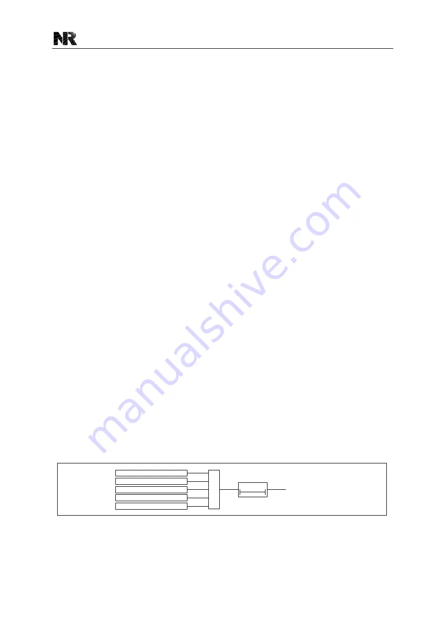
The logic diagram of the synchronism check element for the auto-recloser is shown as below.
Δδ < [25A.phi_Diff]
ΔU < [25A.U_Diff]
Δf < [25A.f_Diff]
&
U
Prot
> [25.U_Lv]
U
Syn
> [25.U_Lv]/[25.U_Comp]
25A.Ok_SynChk
t
ARSynChk
0
Figure 3.17-5 Logic diagram of the synchr onism check element for AR
Where:
“U
Prot
” is the protection voltage value;
Summary of Contents for PCS-9611
Page 1: ...PCS 9611 Feeder Relay Instruction Manual NR Electric Co Ltd...
Page 2: ......
Page 10: ...1 Introduction PCS 9611 Feeder Relay 1 b Date 2014 04 08...
Page 30: ...2 Technical Data PCS 9611 Feeder Relay 2 14 Date 2014 04 08...
Page 36: ...3 Operation Theory PCS 9611 Feeder Relay 3 f Date 2014 04 08...
Page 108: ...4 Supervision PCS 9611 Feeder Relay 4 b Date 2014 04 08...
Page 116: ...5 Management Function PCS 9611 Feeder Relay 5 b Date 2014 04 08...
Page 120: ...5 Management Function PCS 9611 Feeder Relay 5 4 Date 2014 04 08...
Page 218: ...9 Configurable Function PCS 9611 Feeder Relay 9 b Date 2014 04 08...
Page 232: ...9 Configurable Function PCS 9611 Feeder Relay 9 14 Date 2014 04 08...
Page 262: ...11 Installation PCS 9611 Feeder Relay 11 b Date 2014 04 08...
Page 272: ...12 Commissioning PCS 9611 Feeder Relay 12 b Date 2014 04 08...
Page 292: ...13 Maintenance PCS 9611 Feeder Relay 13 b Date 2014 04 08...
Page 296: ...14 Decommissioning and Disposal PCS 9611 Feeder Relay 14 b Date 2014 04 08...
Page 298: ...14 Decommissioning and Disposal PCS 9611 Feeder Relay 14 2 Date 2014 04 08...
Page 300: ...15 Manual Version History PCS 9611 Feeder Relay 15 2 Date 2014 04 08...