


3 Operation Theory
PCS-9611 Feeder Relay
3-6
Date: 2014-04-08
“50/51P1.VCE_x (x: A, B, C)” denotes the state of the voltage control element of the stage 1
overcurrent protection, see
Section 3.3.3
for more details about the voltage control element;
“50/51P1.Dir_x (x: A, B, C)” denotes the state of the directional element of the stage 1
overcurrent protection, see
Section 3.3.4
for more details about the directional element;
“50/51P1.HmBlk_x (x: A, B, C)” denotes the harmonic blocking element of the stage 1
overcurrent protection, see
Section 3.3.5
for more details about the harmonic blocking
element.
The stage 2 overcurrent protection has the same logic diagram with the stage 1 overcurrent
protection, but the operation threshold is its own setting threshold.
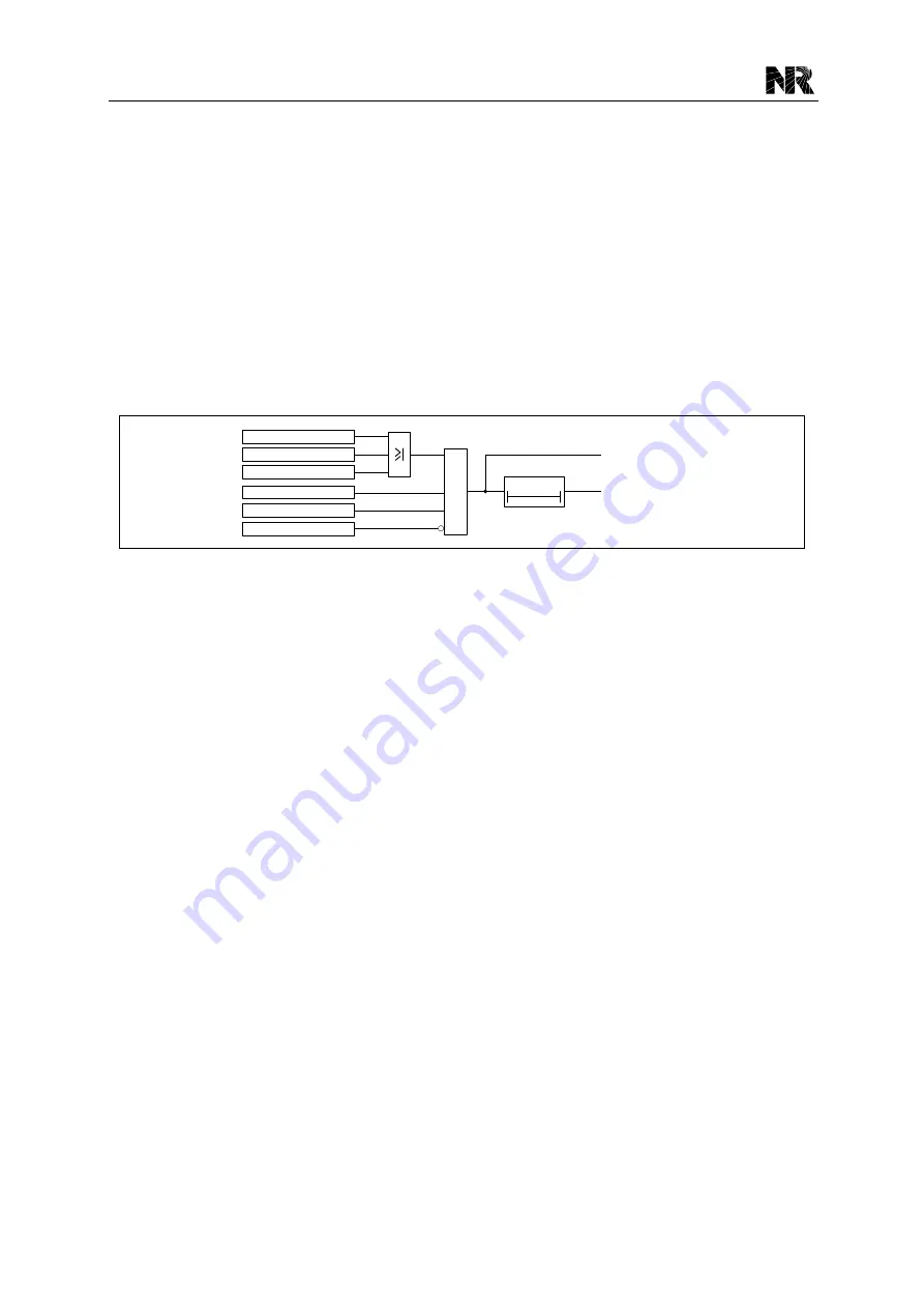
The logic diagram of the stage 5 overcurrent protection is shown in
[50/51P5.Op]
[50/51P5.St]
&
[50/51P5.En1]
[50/51P5.En]
[50/51P5.Blk]
Ia > [50/51P5.I_Set]
Ib > [50/51P5.I_Set]
Ic > [50/51P5.I_Set]
t
OC5
0
Figure 3.3-3 Logic diagram of the stage 5 overcurrent protection
Where:
[50/51P5.I_Set] is the current setting of the stage 5 overcurrent protection;
“t
OC5
” is the setting [50/51P5.t_Op], the time setting of the stage 5 overcurrent protection;
[50/51P5.En] is the logic setting of the stage 5 overcurrent protection;
[50/51P5.En1] is the binary signal for enabling the stage 5 overcurrent protection;
[50/51P5.Blk] is the binary signal for blocking the stage 5 overcurrent protection.
The stage 6 overcurrent protection has the same logic diagram with the stage 5 overcurrent
protection, but the operation threshold is its own setting threshold.
3.3.2 Inverse Definite Minimum Time Overcurrent Protection
The stage 3 and 4 overcurrent protections also can be used as inverse definite minimum time
(IDMT) overcurrent protection if the settings [50/51P3.Opt_Curve] and [50/51P4.Opt_Curve] are
set as
“1”.
Various methods are available to achieve correct relay coordination on a system; by means of
time alone, current alone or a combination of both time and current. Grading by means of current
is only possible where there is an appreciable difference in fault level between the two relay
locations. Grading by time is used by some utilities but can often lead to excessive fault clear ance
times at or near source substations where the fault level is highest. For these reasons the most
commonly applied characteristic in coordinating overcurrent relays is the IDMT type.
The inverse time delayed characteristics comply with the following fo rmula (based on IEC60255-3
Summary of Contents for PCS-9611
Page 1: ...PCS 9611 Feeder Relay Instruction Manual NR Electric Co Ltd...
Page 2: ......
Page 10: ...1 Introduction PCS 9611 Feeder Relay 1 b Date 2014 04 08...
Page 30: ...2 Technical Data PCS 9611 Feeder Relay 2 14 Date 2014 04 08...
Page 36: ...3 Operation Theory PCS 9611 Feeder Relay 3 f Date 2014 04 08...
Page 108: ...4 Supervision PCS 9611 Feeder Relay 4 b Date 2014 04 08...
Page 116: ...5 Management Function PCS 9611 Feeder Relay 5 b Date 2014 04 08...
Page 120: ...5 Management Function PCS 9611 Feeder Relay 5 4 Date 2014 04 08...
Page 218: ...9 Configurable Function PCS 9611 Feeder Relay 9 b Date 2014 04 08...
Page 232: ...9 Configurable Function PCS 9611 Feeder Relay 9 14 Date 2014 04 08...
Page 262: ...11 Installation PCS 9611 Feeder Relay 11 b Date 2014 04 08...
Page 272: ...12 Commissioning PCS 9611 Feeder Relay 12 b Date 2014 04 08...
Page 292: ...13 Maintenance PCS 9611 Feeder Relay 13 b Date 2014 04 08...
Page 296: ...14 Decommissioning and Disposal PCS 9611 Feeder Relay 14 b Date 2014 04 08...
Page 298: ...14 Decommissioning and Disposal PCS 9611 Feeder Relay 14 2 Date 2014 04 08...
Page 300: ...15 Manual Version History PCS 9611 Feeder Relay 15 2 Date 2014 04 08...


