


3 Operation Theory
PCS-9611 Feeder Relay
3-11
Date: 2014-04-08
Under system fault conditions, the fault current vector will lag its nominal phase voltage by an
angle dependent upon the system X/R ratio. It is therefore a requirement that the relay operates
with maximum sensitivity for currents lying in this region. This is achieved by means of the relay
characteristic angle (RCA) setting; this defines the angle by which the current applied to the relay
must be displaced from the voltage applied to the relay to obtain maximum relay sensitivity.
For a close up three-phase fault, all three voltages will collapse to zero and no healthy phase
voltage will be present. For this reason, the relay include s a synchronous polarization feature that
stores the pre-fault positive sequence voltage information and continues to apply it to the
directional overcurrent elements for a time period of 3 fundamental wave cycles, after which, it will
keep the result of the directional element, this ensures that either the instantaneous or the time
delayed directional overcurrent elements will be allowed to operate, even with a three-phase
voltage collapse.
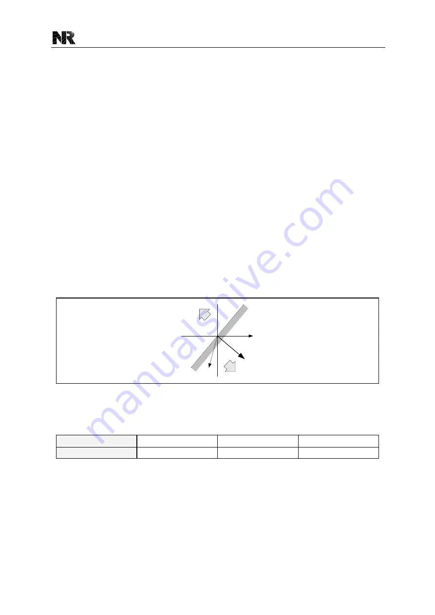
The relay characteristic angle (RCA) is configurable through the setting [ 50/51P.RCA]. A
directional check is performed based on the following criteria:
Directional forward
-90° < (angle(U) - angle(I) - RCA) < 90°
Directional reverse
-90° > (angle(U) - angle(I) - RCA) > 90°
Forward
Reverse
O
U
I
RCA
Figure 3.3-7 Operation characteristic of the OC directional element
The setting [50/51Px.Opt_Dir] (x: 1~4) is used to select the directional mode for the stage x (x:
1~4) overcurrent protection respectively.
Setting Value
0
1
2
Directional Mode
Non-directional
Forward directional
Reverse directional
Any of the first four overcurrent stages may be configured to be directional. When the element is
selected as directional, a VTS block option is available. When the relevant setting is set as
“1”,
operation of the voltage transformer supervision (VTS) will block the stage if the relevant
directional element is in service. When the relevant setting is se t as
“0”, the stage will revert to
non-directional upon operation of the VTS.
The logic diagram of the phase directional overcurrent protection is shown in
. Each
stage of the overcurrent protection can be set with directional element control by its relevant
independent setting respectively. The detailed logic diagram for the phase A directional element
Summary of Contents for PCS-9611
Page 1: ...PCS 9611 Feeder Relay Instruction Manual NR Electric Co Ltd...
Page 2: ......
Page 10: ...1 Introduction PCS 9611 Feeder Relay 1 b Date 2014 04 08...
Page 30: ...2 Technical Data PCS 9611 Feeder Relay 2 14 Date 2014 04 08...
Page 36: ...3 Operation Theory PCS 9611 Feeder Relay 3 f Date 2014 04 08...
Page 108: ...4 Supervision PCS 9611 Feeder Relay 4 b Date 2014 04 08...
Page 116: ...5 Management Function PCS 9611 Feeder Relay 5 b Date 2014 04 08...
Page 120: ...5 Management Function PCS 9611 Feeder Relay 5 4 Date 2014 04 08...
Page 218: ...9 Configurable Function PCS 9611 Feeder Relay 9 b Date 2014 04 08...
Page 232: ...9 Configurable Function PCS 9611 Feeder Relay 9 14 Date 2014 04 08...
Page 262: ...11 Installation PCS 9611 Feeder Relay 11 b Date 2014 04 08...
Page 272: ...12 Commissioning PCS 9611 Feeder Relay 12 b Date 2014 04 08...
Page 292: ...13 Maintenance PCS 9611 Feeder Relay 13 b Date 2014 04 08...
Page 296: ...14 Decommissioning and Disposal PCS 9611 Feeder Relay 14 b Date 2014 04 08...
Page 298: ...14 Decommissioning and Disposal PCS 9611 Feeder Relay 14 2 Date 2014 04 08...
Page 300: ...15 Manual Version History PCS 9611 Feeder Relay 15 2 Date 2014 04 08...


