


3 Operation Theory
PCS-9611 Feeder Relay
3-41
Date: 2014-04-08
[BI_52b] is the binary input for inputting the normally closed contact of the circuit breaker;
[CLP.ShortRst] is the binary signal of the short resetting function;
[CLP.St_50/51] is the binary signal which denotes anyone of th e selected protective elements
picked up;
[CLP.Init] is the binary signal for initiating the cold load pickup logic function (for example, a
binary input signal from other relevant relay);
[CLP.En] is the logic setting of the cold load pickup logic function;
[CLP.Blk] is the binary signal for blocking the cold load pickup logic function;
“t
Cold
” is the setting [CLP.t_Cold], the time setting for ensuring the cold load condition is met;
“t
Rst
” is the setting [CLP.t_Rst], the time setting for resetting the cold load pickup logic
function;
“t
ShortRst
” is the setting [CLP.t_ShortRst], the time setting for fast resetting the cold load pickup
logic function.
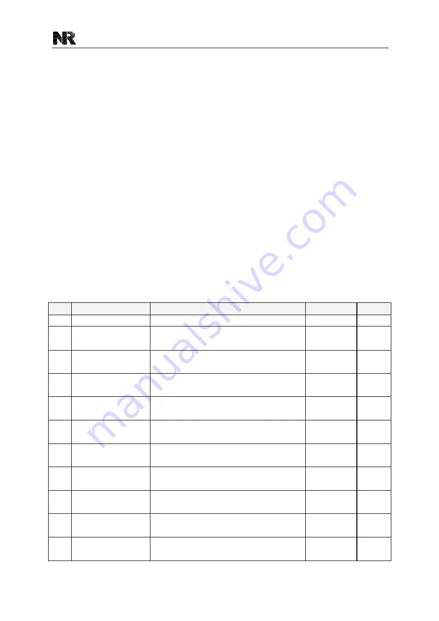
3.11.2 Cold Load Pickup Logic Settings
All the settings of the cold load pickup logic are listed in the following table. For the information
about the common explanation of the settings, see
Section 7.3
.
No.
Menu text
Explanation
Range
Step
1
CLP.Opt_LogicMode
The setting for selecting the cold load condition
1~2
1
2
CLP.t_Cold
The time setting for ensuring the cold load
condition is met
0~4000s
0.001s
3
CLP.t_Rst
The time setting for resetting the cold load pickup
logic
0~4000s
0.001s
4
CLP.t_ShortRst
The time setting for fast resetting the cold load
pickup logic
0~600s
0.001s
5
CLP.En
The logic setting of the cold load pickup logic
function
0~1
1
6
50/51P1.CLP.IMult
The multiple setting of the stage 1 overcurrent
protection when CLP is active
1.00~10.00
0.001
7
50/51P1.CLP.t_Op
The time s etting of the stage 1 overcurrent
protection when CLP is active
0~100s
0.001s
8
50/51P2.CLP.IMult
The multiple setting of the stage 2 overcurrent
protection when CLP is active
1.00~10.00
0.001
9
50/51P2.CLP.t_Op
The time s etting of the stage 2 overcurrent
protection when CLP is active
0~100s
0.001s
10
50/51P3.CLP.IMult
The multiple setting of the stage 3 overcurrent
protection when CLP is active
1.00~10.00
0.001
11
50/51P3.CLP.t_Op
The time s etting of the stage 3 overcurrent
protection when CLP is active
0~100s
0.001s
Summary of Contents for PCS-9611
Page 1: ...PCS 9611 Feeder Relay Instruction Manual NR Electric Co Ltd...
Page 2: ......
Page 10: ...1 Introduction PCS 9611 Feeder Relay 1 b Date 2014 04 08...
Page 30: ...2 Technical Data PCS 9611 Feeder Relay 2 14 Date 2014 04 08...
Page 36: ...3 Operation Theory PCS 9611 Feeder Relay 3 f Date 2014 04 08...
Page 108: ...4 Supervision PCS 9611 Feeder Relay 4 b Date 2014 04 08...
Page 116: ...5 Management Function PCS 9611 Feeder Relay 5 b Date 2014 04 08...
Page 120: ...5 Management Function PCS 9611 Feeder Relay 5 4 Date 2014 04 08...
Page 218: ...9 Configurable Function PCS 9611 Feeder Relay 9 b Date 2014 04 08...
Page 232: ...9 Configurable Function PCS 9611 Feeder Relay 9 14 Date 2014 04 08...
Page 262: ...11 Installation PCS 9611 Feeder Relay 11 b Date 2014 04 08...
Page 272: ...12 Commissioning PCS 9611 Feeder Relay 12 b Date 2014 04 08...
Page 292: ...13 Maintenance PCS 9611 Feeder Relay 13 b Date 2014 04 08...
Page 296: ...14 Decommissioning and Disposal PCS 9611 Feeder Relay 14 b Date 2014 04 08...
Page 298: ...14 Decommissioning and Disposal PCS 9611 Feeder Relay 14 2 Date 2014 04 08...
Page 300: ...15 Manual Version History PCS 9611 Feeder Relay 15 2 Date 2014 04 08...