


7 Settings
PCS-9611 Feeder Relay
7-2
Date: 2014-04-08
19
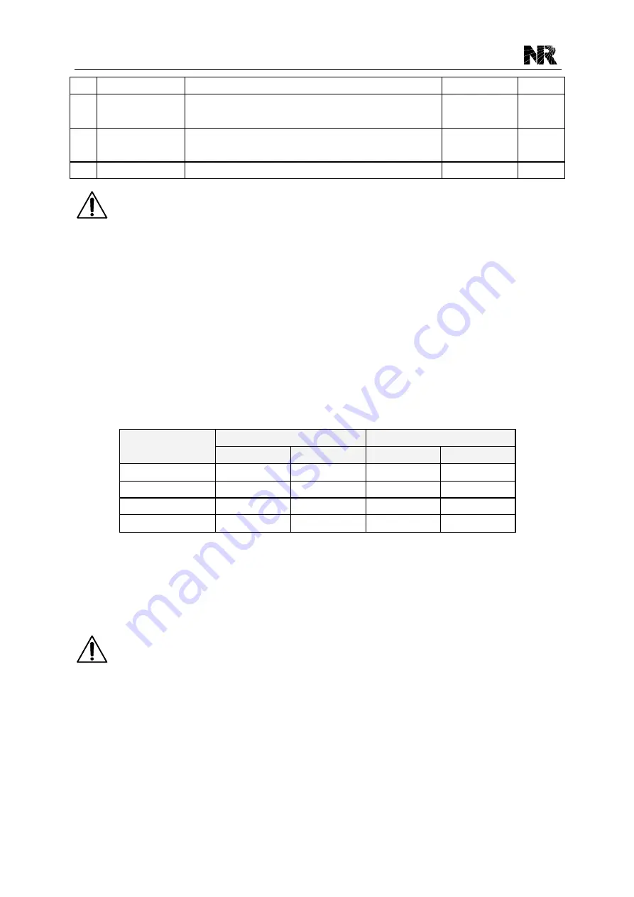
Delt.U2n
Rated secondary value of zero sequence VT
10~200V
0.001V
20
Opt_3I0
Zero sequence current is self calculated
0:from neutral CT 1:self calculated
0~1
1
21
Opt_3U0
Zero sequence voltage is self calculated
0:from neutral VT 1:self calculated
0~1
1
22
Opt_PwrDir
Power Measurement Mode
0~3
1
NOTE!
1. The system settings are related to the protection activities, thus it is necessary to configure
theses settings according to actual conditions.
2. The setting [Opt_3I0] is used to select the No.1 zero sequence current source. Setting the
value of [Opt_3I0] as
“1” means that the No.1 zero sequence current is self-calculated, and
setting the value as
“0” means that the No.1 zero sequence current is derived from specific
zero sequence CT. The default value is
“0” when the equipment is delivered.
3. The setting [Opt_3U0] is used to select the zero sequence voltage source. Setting the value
of [Opt_3U0] as
“1” means that zero sequence voltage is self-calculated, and setting the
value as
“0” means that zero sequence voltage is derived from specific broken delta VT.
4. The setting [Opt_PwrDir] is used to select the power measurement mode.
[Opt_PwrDir]
Active Power
Lagging reactive power
To line
To busbar
To line
To busbar
0
+W
-W
+Var
-Var
1
-W
+W
+Var
-Var
2
+W
-W
-Var
+Var
3
-W
+W
-Var
+Var
7.3 Protection Settings
The protection settings (in the submenu
“
Prot Settings
”) are used to decide the characteristics of
the protective elements. There are up to 10 groups of protection settings in this relay.
NOTE!
Following items should be considered before modifying the protection settings.
1. Before configuring the settings, the setting group must be configured firstly.
2. When a certain setting is of no use, in case of over-elements (such as overcurrent, residual
overcurrent), set the value as upper limit; in case of under-elements (such as under frequency,
under voltage), set the value as lower limit; set the correspo nding time as 100s and disable
corresponding protection element and de-energize the corresponding binary input.
3. In general, for switch onto fault protection and accelerated protection, it is necessary to set a
time delay from decades to 100ms. Thanks to there is no 100ms time delay in the numerical
Summary of Contents for PCS-9611
Page 1: ...PCS 9611 Feeder Relay Instruction Manual NR Electric Co Ltd...
Page 2: ......
Page 10: ...1 Introduction PCS 9611 Feeder Relay 1 b Date 2014 04 08...
Page 30: ...2 Technical Data PCS 9611 Feeder Relay 2 14 Date 2014 04 08...
Page 36: ...3 Operation Theory PCS 9611 Feeder Relay 3 f Date 2014 04 08...
Page 108: ...4 Supervision PCS 9611 Feeder Relay 4 b Date 2014 04 08...
Page 116: ...5 Management Function PCS 9611 Feeder Relay 5 b Date 2014 04 08...
Page 120: ...5 Management Function PCS 9611 Feeder Relay 5 4 Date 2014 04 08...
Page 218: ...9 Configurable Function PCS 9611 Feeder Relay 9 b Date 2014 04 08...
Page 232: ...9 Configurable Function PCS 9611 Feeder Relay 9 14 Date 2014 04 08...
Page 262: ...11 Installation PCS 9611 Feeder Relay 11 b Date 2014 04 08...
Page 272: ...12 Commissioning PCS 9611 Feeder Relay 12 b Date 2014 04 08...
Page 292: ...13 Maintenance PCS 9611 Feeder Relay 13 b Date 2014 04 08...
Page 296: ...14 Decommissioning and Disposal PCS 9611 Feeder Relay 14 b Date 2014 04 08...
Page 298: ...14 Decommissioning and Disposal PCS 9611 Feeder Relay 14 2 Date 2014 04 08...
Page 300: ...15 Manual Version History PCS 9611 Feeder Relay 15 2 Date 2014 04 08...


