Nordson Sealant Equipment PRO-METER V2K Customer Product Manual Download Page 111

Disassembly and Assembly

11-9

Part 7440274

 2017 Nordson Corporation

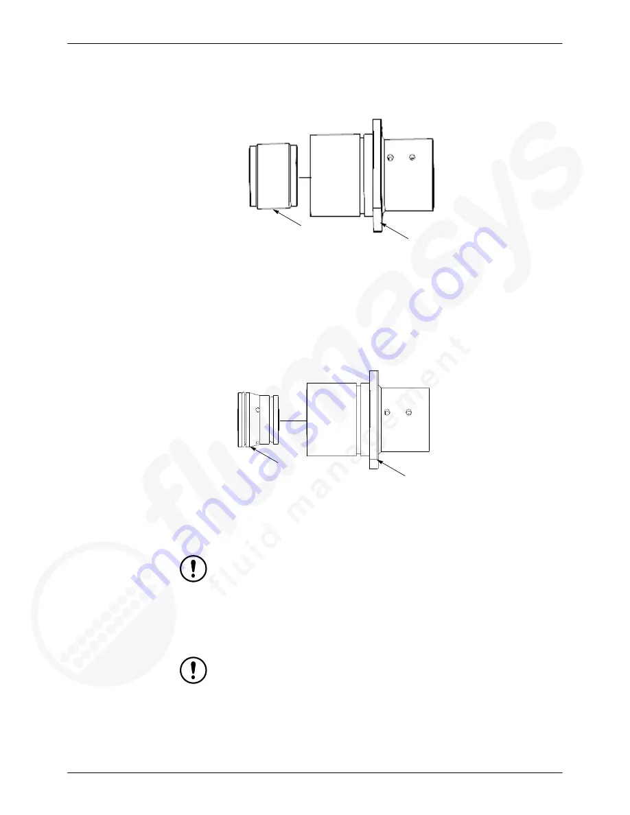
16. Remove bearing (2) from metering cylinder body (1).

1

2

Figure 11-70 Bearing Removal From Metering Cylinder Body

17. Remove lantern ring (2) from metering cylinder body (1).

NOTE:  

Utilize seal removal tool, or equivalent, to remove lantern ring from

metering cylinder body.

1

2

Figure 11-71 Lantern Ring Removal From Metering Cylinder Body

18. Utilize a plastic pick with a blunt tip, or equivalent tool, to remove O

ring

(1) from lantern ring (4). See Figure 11-72.

CAUTION:


Do not use sharp or pointed tools to remove O

ring.

Do not reuse O

ring.

19. Utilize a plastic pick with a blunt tip, or equivalent tool, to remove cap (2)

from lantern ring (4). See Figure 11-72.

CAUTION:


Do not use sharp or pointed tools to remove cap.

Do not reuse cap.

Summary of Contents for PRO-METER V2K

Page 1: ...al support call the Nordson Sealant Equipment customer support at 734 459 8600 or contact your local Nordson Sealant Equipment Representative This document is subject to change without notice Please c...

Page 2: ...which is protected by copyright Original copyright date 08 2016 No part of this document may be photocopied reproduced or translated to another language without the prior written consent of Nordson C...

Page 3: ...ogenated Hydrocarbon Solvent Hazards 1 6 Action in the Event of a Malfunction 1 6 Disposal 1 6 Description 2 1 Meter 2 1 Meter Assembly Standard Components 2 2 Meter Connections 3 1 Connection Overvie...

Page 4: ...scriptions 7 2 Auto Flow Mode 7 2 Auto Shot Mode 7 2 Manual Flow Mode 7 2 Manual Shot Mode 7 2 Operation 7 3 Maintenance 8 1 Consumables 8 2 Preparation For Maintenance and Service 8 3 Air Pressure Re...

Page 5: ...c Valve Manifold 10 35 Removal 10 35 Installation 10 37 Pneumatic Valve Manifold Solenoid 10 38 Removal 10 38 Installation 10 39 Power Supply Fuse 10 40 Removal 10 40 Installation 10 42 Power Supply C...

Page 6: ...ispense 1 14 2 Dispense 2 14 3 Faults Warnings 1 and 2 14 4 Faults Warnings 1 14 4 Faults Warnings 2 14 5 Interlock Status 14 7 Material Pressure 14 8 Material Pressure History 14 9 Meter Status 14 10...

Page 7: ...2 Customer Product Manual 15 3 Pro Meter V2K Assembly Top Level Assembly 15 3 Pro Meter V2K Basic Assembly 15 6 Base Plate Assembly 15 16 Cover Assembly 15 21 Gravity Feed Tanks If Equipped 15 23 HMI...

Page 8: ......

Page 9: ...afety rules and regulations and are physically capable of performing their assigned tasks Intended Use Use of Nordson equipment in ways other than those described in the documentation supplied with th...

Page 10: ...t While operating manual dispense valves make sure you are grounded Wear electronically conductive gloves or a grounding strap connected to the dispense valve handle or other true earth ground Do not...

Page 11: ...ous traumatic injury It is important to treat the injury surgically as soon as possible Do not delay treatment to research toxicity Toxicity is a concern with some exotic coatings injected directly in...

Page 12: ...tions of volatile materials or vapors Refer to local codes or your SDS for guidance Do not disconnect live electrical circuits while working with flammable materials Shut off power at a disconnect swi...

Page 13: ...eing evaluated Equipment to be grounded includes but is not limited to the floor of the spray area operator platforms hoppers photoeye supports and blow off nozzles Personnel working in the spray area...

Page 14: ...erial SDS or contact your material supplier for more information If you must use halogenated hydrocarbon solvents contact your Nordson Sealant representative for information about compatible Nordson S...

Page 15: ...nts consist of an air actuator ball valve assemblies metering cartridge assemblies power supply assembly valve manifold micro PLC and an interactive HMI control panel Each metering cartridge assembly...

Page 16: ...charge port where it is later dispensed via a dispense valve 3 Ball valve serves as the inlet valve for the dispense system 4 Metering cartridge assembly metering rods along with associated seals and...

Page 17: ...Refer to Maintenance Preparation For Maintenance And Service page 8 3 for additional information Apply Loctite properly to fasteners Refer to Thread Locker Application page 5 2 for Loctite applicatio...

Page 18: ...e as this may cause material to pack and harden Only apply removable thread locker and sealant as specified by the procedures in this manual Electrical Harness Connectors Connect electrical harness co...

Page 19: ...metering cartridge assembly primary seal Material ob served from the weep plug denotes metering cartridge assembly primary seal failure 7 Metering cylinder housing oil cup allows Seal Sav r oil to be...

Page 20: ......

Page 21: ...troke 5 50 inch 139 7 mm Micro PLC Refer to Product Literature Pneumatic valve Manifold Refer to Product Literature System decibels maximum 63 6 dBA System dimensions 30 38 inches 771 65 mm long x 17...

Page 22: ......

Page 23: ...e properly to fasteners Refer to Loctite Product Application Cleanup And Storage page 5 2 for Loctite application information WARNING Any material injected into flesh can cause severe injury or death...

Page 24: ...ld be allowed to run down the internal threads until it reaches the bottom of the blind hole Product sets in approximately 10 minutes and cures in 24 hours Sealing Applications Ensure the work area is...

Page 25: ...5 3 Part 7440274 2017 Nordson Corporation Storage Ensure container holding product is completely sealed after use Do not allow product to freeze Store product in a dry location Optimal storage tempera...

Page 26: ......

Page 27: ...tion page 5 1 for Loctite application information Clean any material that has spilled Be sure to follow all applicable safety and environmental guidelines when cleaning spilled material Refer to Safet...

Page 28: ...without the gravity tanks installed 31 51 inches 800 35 mm tall with the gravity tanks installed Air Line Routing Refer to the Pneumatic Circuit Drawing s for air line routing information Ensure air l...

Page 29: ...en captures 1 Connect discharge port hoses to the metering cartridge assemblies Discharge port hoses connect to both sides of the dispense system Discharge port hose Figure 6 3 Discharge Port Hose Con...

Page 30: ...egulator assembly 6 Switch Pro Meter V2K power switch to the ON position 7 Proceed to Main Menu HMI Pendant Screen 8 Select SETUP LOGIN push button to proceed to Setup Login HMI Pendant screen 9 Log i...

Page 31: ...ir bubbles are no longer observed in the clear tubing 15 Close bleed valves located on the metering cartridge assemblies 16 Proceed to the Dispense 1 HMI Pendant Screen and note the following Select M...

Page 32: ...roceed to Level 2 Setup HMI Pendant Screen Select RESET PASSWORD to proceed to Reset Password HMI Pendant Screen Select Reset Password push button and follow prompts Air Actuator Flow Adjustment See F...

Page 33: ...llowing Enter the Scaled Distance mm valve into the 0 mm Cal Value mA data entry field Proceed to Valve Setup HMI Pendant screen See Step 2 Press the Return Rods push button so that the meter is fully...

Page 34: ...bration in instances where there is an extreme difference in viscosity regarding materials Adjustment of lead lag calibration optimizes the mix of material 1 Loosen lead lag jam nut 2 2 Adjust lead la...

Page 35: ...evel sensors 1 Utilize a small flat head screw driver to gently pry open low level sensor adjustment screw access cover B 2 Turn low level sensor adjustment screw A slowly counter clockwise with a sma...

Page 36: ...on the pressure transducer 2 Utilize calibration record as a basis to enter control panel calibration data 3 Turn control panel OFF 4 Install new pressure transducer Refer to Removal and Installation...

Page 37: ...OTE Refer to Screen Descriptions page 14 1 to review illustrative screen captures 1 Proceed to the Dispense 1 HMI Pendant Screen 2 Select Manual Mode push button 3 With the primary cover removed adjus...

Page 38: ...Corporation Strike stop contacts limit switch Figure 6 10 Meter Empty Position 4 Turn OFF Manual Mode via the Dispense 1 HMI Pendant Screen 5 Adjust the strike stop position via the strike screw nut u...

Page 39: ...d environmental guidelines when cleaning spilled material Refer to Safety page 1 1 for additional information WARNING Any material injected into flesh can cause severe injury or death Keep body parts...

Page 40: ...eload as long as a signal is received from the external source Auto Shot Mode Auto Shot Mode accommodates the completion of several automated dispense shots and reloads as dictated by the shot counter...

Page 41: ...I Pendant Screen and enable the Machine Interlock Mode push button 7 From the Level 1 Setup Menu HMI Pendant Screen establish the following parameters System delay specifications via the Miscellaneous...

Page 42: ......

Page 43: ...Loctite application information Clean any material that has spilled Be sure to follow all applicable safety and environmental guidelines when cleaning spilled material Refer to Safety page 1 1 for ad...

Page 44: ...per Blu 7437105 Applied to slide block zerk fittings to lub ricate slide rail Refer to Maintenance Preventative Maintenance Schedule page 8 5 for additional information Loctite 242 N A Apply when proc...

Page 45: ...itting from filter regulator assembly air input port 1 located on power supply assembly 1 Figure 8 11 Quick Connect Air Fitting 3 Remove the secondary cover 2 from the primary cover 1 CAUTION Utilize...

Page 46: ...e screws located at the center of the pneumatic valve manifold solenoid See Figure 8 13 7 Slightly lift pneumatic valve manifold solenoid middle 1 to allow air to escape See Figure 8 13 1 Figure 8 13...

Page 47: ...uidelines when cleaning spilled material Refer to Safety page 1 1 for additional information 3 Monitor pressure transducer readings via teach pendant HMI to verify that system material pressure is at...

Page 48: ...anks Inspect for material leaks Inspect 5 Min Replace 30 Min Guide rod Inspect for scoring and straightness Inspect 15 Min Replace 30 Min Material fittings and hoses Inspect for material leaks Inspect...

Page 49: ...ation Table 8 5 Preventative Maintenance Schedule contd Strike screw Inspect for straightness debris damage to threads Inspect 15 Min Replace 1 2 Hrs Pneumatic valve mani fold Inspect for air leaks fr...

Page 50: ......

Page 51: ...Loctite application information Clean any material that has spilled Be sure to follow all applicable safety and environmental guidelines when cleaning spilled material Refer to Safety page 1 1 for add...

Page 52: ...ufficient air pressure Ensure solenoid valves are functioning properly Metering cartridge assembly malfunction Check for sufficient supply pressure Inspect wearable parts for wear and damage Inspect m...

Page 53: ...page 5 1 for Loctite application information Clean any material that has spilled Be sure to follow all applicable safety and environmental guidelines when cleaning spilled material Refer to Safety pa...

Page 54: ...s spilled Be sure to follow all applicable safety and environmental guidelines when cleaning spilled material Refer to Safety page 1 1 for additional information 1 Remove metering cartridge assemblies...

Page 55: ...c valve manifold See Figure 10 43 Be careful not to kink or otherwise damage electrical wiring harness 5 Remove cap screws securing air valve control shelf to strike end bracket 6 Carefully pivot air...

Page 56: ...ike end bracket Remove washer from strike end screw if necessary Utilize pick or equivalent tool to remove bushing from strike end bracket if necessary CAUTION Do not reuse bushing 9 Utilize an adjust...

Page 57: ...alve 1 from air actuator if necessary NOTE It is possible to remove the flow control valve and flow control valve bushing from the air actuator as an assembly 1 1 Figure 10 14 Flow Control Valve Assem...

Page 58: ...or into metering cylinder housing by hand until air actuator rod is snug with the carriage Loosely install and then tighten socket head cap screws securing air actuator to metering cylinder housing in...

Page 59: ...ovable thread locker to air actuator rod threads Apply Loctite 242 or 248 or equivalent removable thread locker to threads of socket head cap screws securing strike end bracket to base plate Apply Loc...

Page 60: ...her related documentation Clean any material that has spilled Be sure to follow all applicable safety and environmental guidelines when cleaning spilled material Refer to Safety page 1 1 for additiona...

Page 61: ...n Corporation 5 Remove bolts and lock washers securing ball valve to ball valve assembly Figure 10 16 Removal Of Ball Valve From Ball Valve Assembly 6 Remove ball valve 1 from ball valve flange 2 1 2...

Page 62: ...Closed ball valve is denoted by the indicator positioned horizontally Figure 10 18 Ball Valve Depicted In Closed Position 7 Remove air fittings from ball valve if necessary 8 Unscrew ball valve flange...

Page 63: ...install socket head screws securing primary cover to primary cover bracket LH RH and then tighten until they are snug Hand tighten air fittings so that they are snug if removed CAUTION Ensure the ball...

Page 64: ...al guidelines when cleaning spilled material Refer to Safety page 1 1 for additional information 1 Remove air actuator Refer to Removal and Installation Air Actuator page 10 2 for air actuator removal...

Page 65: ...et head cap screws and tighten in a criss cross pattern to 13 5 N m 10 0 ft lb Loosely install carriage hard stop socket head cap screws and tighten in a criss cross pattern to 13 5 N m 10 0 ft lb CAU...

Page 66: ...sure to follow all applicable safety and environmental guidelines when cleaning spilled material Refer to Safety page 1 1 for additional information 1 Remove metering cartridge assembly Refer to Remov...

Page 67: ...ote the following Hand tighten fasteners securing cylinder position sensor brackets to air actuator so that they are snug CAUTION Be careful not to damage cylinder position sensor Do not reuse damaged...

Page 68: ...ure to follow all applicable safety and environmental guidelines when cleaning spilled material Refer to Safety page 1 1 for additional information 1 Place ball valve located just below gravity tank i...

Page 69: ...1 2 Figure 10 24 Gravity Tank Removal From Gravity Tank Bracket 5 Remove locking pins 1 from cam lock coupling 1 Figure 10 25 Locking Pin Removal From Cam Lock Coupling 6 Release the cam lock coupling...

Page 70: ...sensor if equipped Refer to Removal and Installation Low Level Sensor page 10 26 for low level sensor removal procedure Installation Installation of the gravity tank is in the reverse order of remova...

Page 71: ...e safety instructions in this document and all other related documentation Clean any material that has spilled Be sure to follow all applicable safety and environmental guidelines when cleaning spille...

Page 72: ...imit switch mount Installation Installation of limit switch is in the reverse order of removal Note the following Loosely install limit switch socket head cap screws and tighten to 1 7 N m 15 6 in lb...

Page 73: ...ment and all other related documentation Clean any material that has spilled Be sure to follow all applicable safety and environmental guidelines when cleaning spilled material Refer to Safety page 1...

Page 74: ...it switch mount Installation Installation of limit switch is in the reverse order of removal Note the following Loosely install limit switch socket head cap screws and tighten to 1 7 N m 15 6 in lb Lo...

Page 75: ...cumentation Clean any material that has spilled Be sure to follow all applicable safety and environmental guidelines when cleaning spilled material Refer to Safety page 1 1 for additional information...

Page 76: ...moval From Linear Speed Control 4 Unscrew linear speed control from metering cylinder housing 5 Utilize channel locks or equivalent tool to loosen linear speed control bushing Figure 10 33 Linear Spee...

Page 77: ...of removal Note the following Hand tighten linear speed control bushing until it is snug Hand tighten linear speed control until it is snug Install gravity tank bracket to air actuator socket head ca...

Page 78: ...plicable safety and environmental guidelines when cleaning spilled material Refer to Safety page 1 1 for additional information 1 Disconnect electrical harness connector from low level sensor CAUTION...

Page 79: ...ted documentation Clean any material that has spilled Be sure to follow all applicable safety and environmental guidelines when cleaning spilled material Refer to Safety page 1 1 for additional inform...

Page 80: ...primary cover to primary cover bracket LH RH 3 Remove primary cover from dispense system 4 Disconnect electrical harness connector from pressure transducer if equipped CAUTION Do not kink or otherwis...

Page 81: ...metering rod 1 Figure 10 38 Metering Rod Collar Removal From Metering Rod Remove metering rod mounting collar from metering rod NOTE Remove the metering rod mounting collar in halves 7 Remove socket...

Page 82: ...cartridge assembly is in the reverse order of removal Note the following Tighten metering cartridge assembly socket head cap screws to 13 5 N m 10 0 ft lb Hand tighten plug so that it is snug if remov...

Page 83: ...loosen lead lag nut to facilitate installation of metering rod collar Figure 10 41 Metering Rod Collar Installation CAUTION Apply Loctite 577 or equivalent thread sealer to threads of reducer plug an...

Page 84: ...uctions in this document and all other related documentation Clean any material that has spilled Be sure to follow all applicable safety and environmental guidelines when cleaning spilled material Ref...

Page 85: ...lease it from Micro PLC Figure 10 43 Removal Of Options Harness Block From Micro PLC 5 Remove Ethernet cable from micro PLC 6 Utilize screwdriver or equivalent to release green terminal blocks from ea...

Page 86: ...tion Installation of micro PLC is in the reverse order of removal Note the following Hand tighten green terminal block screws until they are snug Loosely install socket head screws securing primary co...

Page 87: ...uctions in this document and all other related documentation Clean any material that has spilled Be sure to follow all applicable safety and environmental guidelines when cleaning spilled material Ref...

Page 88: ...e located on the underside of the air valve control shelf Pivot the air valve control shelf upwards if necessary to access nuts and lock washers Proceed as follows Disconnect air lines and green termi...

Page 89: ...r valve control shelf 3 and then tighten in a criss cross pattern to 3 9 N m 34 8 in lb Loosely install air valve control shelf bracket to strike end plate cap screws and then tighten to 13 5 N m 10 0...

Page 90: ...safety instructions in this document and all other related documentation Clean any material that has spilled Be sure to follow all applicable safety and environmental guidelines when cleaning spilled...

Page 91: ...tic valve manifold solenoid Figure 10 47 Removal Of Pneumatic Valve Solenoid 1 of 2 Figure 10 48 Removal Of Pneumatic Valve Solenoid 2 of 2 Installation Installation of the pneumatic valve manifold so...

Page 92: ...following tasks Follow the safety instructions in this document and all other related documentation Clean any material that has spilled Be sure to follow all applicable safety and environmental guide...

Page 93: ...ion 10 41 Part 7440274 2017 Nordson Corporation Figure 10 50 Fuse Removal From Power Supply Switch 2 of 4 Figure 10 51 Fuse Removal From Power Supply Switch 3 of 4 Figure 10 52 Fuse Removal From Power...

Page 94: ...Removal and Installation 10 42 Part 7440274 2017 Nordson Corporation Installation Installation of the power supply fuse is in the reverse order order of removal...

Page 95: ...cable safety and environmental guidelines when cleaning spilled material Refer to Safety page 1 1 for additional information 1 Remove the secondary cover 2 from the primary cover 1 CAUTION Utilize han...

Page 96: ...Supply Cover Removal 2 of 2 Installation Installation of power supply cover is in the reverse order of removal Note the following Loosely install socket head cap screws lock washers and nuts securing...

Page 97: ...ing tasks Follow the safety instructions in this document and all other related documentation Clean any material that has spilled Be sure to follow all applicable safety and environmental guidelines w...

Page 98: ...f removal Note the following Loosely install socket head cap screws lock washers washers and nuts securing power supply cover to power supply and tighten to 1 7 N m 15 6 in lb CAUTION Apply Loctite 24...

Page 99: ...er to Safety page 1 1 for additional information 1 Remove power supply cover Refer to Removal and Installation Power Supply Cover page 10 40 for power supply cover removal procedure 2 Remove socket he...

Page 100: ...t has spilled Be sure to follow all applicable safety and environmental guidelines when cleaning spilled material Refer to Safety page 1 1 for additional information 1 Disconnect electrical harness co...

Page 101: ...y port securing pressure transducer with Chevron Petrolatum Snow Do not attempt to scrape hardened material from the pressure transducer Attempting to remove hardened material may result in component...

Page 102: ......

Page 103: ...page 5 1 for Loctite application information Clean any material that has spilled Be sure to follow all applicable safety and environmental guidelines when cleaning spilled material Refer to Safety pa...

Page 104: ...20 19 17 16 18 15 Figure 11 59 Metering Cartridge Assembly Exploded View 1 Metering rod 8 Cap 15 Nut 2 Socket head cap screws 9 Seal 16 O ring 3 O ring 10 O ring 17 Parbak ring 4 Rod oil retainer 11...

Page 105: ...ment and all other related documentation Clean any material that has spilled Be sure to follow all applicable safety and environmental guidelines when cleaning spilled material Refer to Safety page 1...

Page 106: ...2 3 4 Figure 11 60 Removal Of Base From Tube 4 Utilize a plastic pick with a blunt tip or equivalent tool to remove O ring 2 and Parbak ring 3 from metering cylinder base 1 1 2 3 Figure 11 61 O ring...

Page 107: ...4 from tie rods 1 See Figure 11 62 7 Remove tube 2 from metering cylinder body 3 See Figure 11 62 8 Utilize a plastic pick with a blunt tip or equivalent tool to remove Parbak ring 1 and O ring 2 fro...

Page 108: ...ing retainer 3 Figure 11 64 Removal Of Oil Retainer To Bearing Retainer Fasteners 10 Remove metering rod 2 from metering cartridge assembly 1 1 2 Figure 11 65 Removal Of Metering Rod From Metering Car...

Page 109: ...with a blunt tip or equivalent tool to remove O ring 1 from rod oil retainer 2 CAUTION Do not use sharp or pointed tools to remove O ring Do not reuse O ring 1 2 3 Figure 11 67 Removal Of O rings From...

Page 110: ...etering Cylinder Body CAUTION Utilize a spanner wrench or equivalent tool to unscrew bearing retainer from metering cylinder body 15 Utilize a plastic pick with a blunt tip or equivalent tool to remov...

Page 111: ...antern ring from metering cylinder body 1 2 Figure 11 71 Lantern Ring Removal From Metering Cylinder Body 18 Utilize a plastic pick with a blunt tip or equivalent tool to remove O ring 1 from lantern...

Page 112: ...or pointed tools to remove seal Do not reuse seal 21 Utilize a plastic pick with a blunt tip or equivalent tool to remove O ring 5 from lantern ring 4 See Figure 11 72 CAUTION Do not use sharp or poi...

Page 113: ...o metering cylinder body so that they are snug Loosely install nuts 15 and tighten to 13 5 N m 10 0 ft lb See Figure 11 59 Hand tighten bearing retainer until it is snug CAUTION Do not reuse bearings...

Page 114: ...ill contact nuts and metering cylinder body The surface of the metering rod is ground to specification and should be protected from damage during handling Utilize a spanner wrench or equivalent tool t...

Page 115: ...els 800x480 WVGA Type TFT touchscreen wide LCD ELECTRICAL Communication port Separate RS232 and RS422 RS485 connectors Ethernet 10 100 Mbps 1 Internal Storage 256 MB Programming port USB device port E...

Page 116: ...on Table 12 6 PanelView C800 Specifications contd MECHANICAL Accessories 7 inch adapter plate kit part 2711R APK7 Cutout dimensions 4 9x7 1 125 x 179 mm Mounting mechanism Quick lever clips Overall di...

Page 117: ...an option that has not been selected for the particular application Push Buttons See Figure 13 77 Push buttons are shown as raised rectangular objects containing text General operational control butt...

Page 118: ...a data entry push button on the screen will open a pop up keypad that will allow the operator to enter new data given preset limits defined by the PLC Pressing the ENTER key on the keypad will complet...

Page 119: ...Common Screen Description Elements 13 3 Part 7440274 2017 Nordson Corporation Pilot light indicator Figure 13 76 Pilot Light Indicator Example...

Page 120: ...Common Screen Description Elements 13 4 Part 7440274 2017 Nordson Corporation Push button Figure 13 77 Push button Example...

Page 121: ...Common Screen Description Elements 13 5 Part 7440274 2017 Nordson Corporation Push button with indicator light Figure 13 78 Push Button With Indicator Light Example...

Page 122: ...Common Screen Description Elements 13 6 Part 7440274 2017 Nordson Corporation Data display Figure 13 79 Data Display Example...

Page 123: ...Common Screen Description Elements 13 7 Part 7440274 2017 Nordson Corporation Data entry field Figure 13 80 Data Entry Field Example...

Page 124: ...Common Screen Description Elements 13 8 Part 7440274 2017 Nordson Corporation Dashboard indicator Figure 13 81 Dashboard Indicator Example...

Page 125: ...Common Screen Description Elements 13 9 Part 7440274 2017 Nordson Corporation Bar graph Figure 13 82 Bar Graph Example...

Page 126: ...s are located along the bottom of the screen On normal operation screens the button to return to the Main Menu screen is usually found in the lower right corner On most setup screens this position is...

Page 127: ...Common Screen Description Elements 13 11 Part 7440274 2017 Nordson Corporation Mode indicator Status indicator Title bar Navigation Button Figure 13 83 Typical Screen Layout...

Page 128: ......

Page 129: ...gate to any screen The indicator at the top left of the screen is the mode indicator If no mode is selected the box will appear grey with No Mode text displayed The box will appear yellow while in Aut...

Page 130: ...eloading Dispensing Complete Purging are also present This screen also has push buttons to engage Auto Shot Mode Dispense and Reload Data displays are also present reflecting high and low volume psi A...

Page 131: ...psi and the time remaining until a purge is initiated A shot counter data display is present along with bar graphs to reflect system full empty status cylinder position and material pressure A push bu...

Page 132: ...p indicates that the Emergency Stop button on the control panel has been depressed To reset the system release the Emergency Stop button and press the Reset Faults navigation button on the Faults Warn...

Page 133: ...sure faults in the system Note the following High Pressure is a fault indicating that the observed pressure exceeds the high pressure limit Low Dispense Pressure is a fault indicating that the observe...

Page 134: ...orporation Resets faults Directs operators to the Faults Warnings 1 Screen Directs operators to the Main Menu Screen System indicators reflect different faults and warnings which could occur during op...

Page 135: ...operator to troubleshoot the system The inputs from the operator to the machine are OK to Purge Dispense Command and Reload Command The outputs from the machine to the operator are Dispense Ready Dis...

Page 136: ...will fault and stop the system if the pressure drops below the programmed limit during an active dispense cycle The Reload Limit must be met or exceeded before the pre pressure sequence can begin The...

Page 137: ...ssure data boxes record the highest and lowest pressures for respective sides of the meter Recorded pressures can be reset to 0 psi and re recorded until they are reset again The status indicators alo...

Page 138: ...tatus of inputs outputs and options These areas illuminate when each valve switch or sensor is activated This screen is primarily used as a troubleshooting tool Directs operators Directs operators to...

Page 139: ...ent options These options control several parts of the system It is important to note that selecting various options only configures the PLC and operator interface software for these options Additiona...

Page 140: ...nitiate the purge cycle by pressing the Manual Purge push button or clear the nozzle by initiating any other dispensing operation If for some reason the nozzle is not purged before the purge timer rea...

Page 141: ...etup and Level 2 Setup Screens This interface also allows the operator to log in and out Directs operators to the Level 1 Setup Screen Directs operators to the Level 2 Setup Screen Directs operators t...

Page 142: ...assword Confirm Exit To Config Mode See Figure 14 96 This screen allows the operator the option of either exiting to configuration mode or navigating back to the Level 2 Setup Screen Directs operators...

Page 143: ...14 97 This screen allows the operator to specify the metering cartridge assembly tube diameter This screen also displays the amount of material dispensed per shot Directs operators to Level 1 Setup S...

Page 144: ...This screen has a push button with an indicator light to denote Flow Mode Auto Retract Enable There is also a data entry field for operators to specify the Auto Reload Delay sec Directs operators to M...

Page 145: ...es of the dispense system The Dispense Ready Dispense Complete and Purge Warning push buttons all send signals to the automation source The push buttons are accompanied by indicators to confirm a sign...

Page 146: ...t 7440274 2017 Nordson Corporation Level 1 Setup Menu See Figure 14 100 Push buttons navigate the operator to other screens This screen accommodates easy navigation to other screens Figure 14 100 Leve...

Page 147: ...t 7440274 2017 Nordson Corporation Level 2 Setup Menu See Figure 14 101 Push buttons navigate the operator to other screens This screen accommodates easy navigation to other screens Figure 14 101 Leve...

Page 148: ...to specify the length in time that the machine waits before sending a signal to the automation source Delays may established for the following Cylinder Extend Cylinder Retract Direction Change Dispens...

Page 149: ...rent options These options control several parts of the system It is important to note that selecting various options only configures the PLC and operator interface software for these options Addition...

Page 150: ...then show the calibrated distance with no correction for the zero offset The displayed distance may be positive or negative due to the pre load placed on the cylinder position sensor when it is instal...

Page 151: ...and the dispense cycle will stop This helps guard against leaks broken hoses etc Reload Pressure Limit psi During a reload cycle the inlet valve will stay open until the carriage reaches its home pos...

Page 152: ...Screen Descriptions 14 24 Part 7440274 2017 Nordson Corporation Directs operators to Misc Pressure Screen Directs operators to Level 1 Setup Screen Figure 14 105 Pressure Limits Setup HMI Interface...

Page 153: ...ield Enter the appropriate calibration values from the Certificate of Calibration for that transducer into the 0 psi Cal mA and Full Scale psi Cal value ma interface entry fields The Scaled Pressure a...

Page 154: ...ies scaled pressure for high and low volume side of the meter Allows entry of pres sure sensor full scale psi Allows entry of psi cal value Allows entry of the full scale psi cal val mA Allows zero of...

Page 155: ...se Pressure Fault Duration sec A push button has been conveniently provided to allow operators to illustrate pressure readings in PSI or BAR Specification of these values directly impacts the info gra...

Page 156: ...r of shots per purge the purge warning time and purge fault time The Purge Warning Time is the time period the machine will wait before a purge warning signal is generated The Purge Fault Time is the...

Page 157: ...allows the operator to update passwords Operators are able to customize passwords for level 1 and level 2 screen access The default user name is 2 The default password is also 2 Directs operators to L...

Page 158: ...specify the Shot Per Cycle Retract Pos mm and Extend Pos mm The entry of position location data allows the PLC to display calculated volume output when a cylinder position sensor is not utilized Dire...

Page 159: ...ng Overrides are deactivated whenever the operator leaves this screen The dispense valve must be open when advancing the air cylinder to allow metered material to flow Allowing material to flow will p...

Page 160: ......

Page 161: ...ns the part cannot be ordered separately The Description column gives the part name as well as its dimensions and other characteristics when appropriate Indentions show the relationships between assem...

Page 162: ...ote 0000000 Assembly 1 1 000000 S Subassembly 2 A 2 000000 S S Part 1 Item Part Description Quantity Note S S S S S S S S S S NOTE A B X AR As Required NS Not Shown Continued 3 Column Parts List Part...

Page 163: ...CHT DWG TOP LVL ASSY PRO MTR V2K 1 10 7440581 S ASSEMBLY BASIC PRO MTR V2K 1 20 7440519 S CARTRIDGE MTR ASSY 250 PM V2K AA 1 30 7440518 S CARTRIDGE MTR ASSY 1 125 PM V2K AA 1 40 7440515 S COVER ASSY...

Page 164: ...Parts 15 4 Part 7440274 E 2017 Nordson Corporation 2600 163 XXX 80 10 Figure 15 112 Pro MeterR Top Level Assembly 1 of 2...

Page 165: ...Parts 15 5 Part 7440274 E 2017 Nordson Corporation 2600 163 XXX 50 30 10 70 70 20 50 Figure 15 113 Pro MeterR Top Level Assembly 2 of 2...

Page 166: ...POWER SUPPLY 24VDC ASSY PRO MTR V2K 1 19 7430948 S REDUCER 1 2IN M X 3 8IN F 2 20 1607012 S CYLINDER AIR 100MM BORE X 144MM STK 1 21 7436106 S SCREW BHC M5X0 8X15MM 2 22 7436107 S SCREW BHC M6X1X12MM...

Page 167: ...12 55 7436652 S SCREW SHC BL OX M6X40 4 56 7440275 S VALVE SLND 3 STA D SUB PM VE 1 57 7440528 S BELLOWS LINEAR SLIDE 25MMX330MM 1 58 7440529 S LINEAR SLIDE SYSTEM 25MMX330MM 1 59 7430419 S CONNECTOR...

Page 168: ...Parts 15 8 Part 7440274 E 2017 Nordson Corporation 1700 070 000 18 15 36 42 Figure 15 114 Pro MeterR Basic Assembly 1 of 8...

Page 169: ...Parts 15 9 Part 7440274 E 2017 Nordson Corporation 1700 070 000 22 25 14 Figure 15 115 Pro MeterR Basic Assembly 2 of 8...

Page 170: ...Parts 15 10 Part 7440274 E 2017 Nordson Corporation 1700 070 000 18 51 59 60 1 66 67 8 31 9 10 50 25 54 65 64 Figure 15 116 Pro MeterR Basic Assembly 3 of 8...

Page 171: ...Parts 15 11 Part 7440274 E 2017 Nordson Corporation 1700 070 000 62 63 61 57 58 Figure 15 117 Pro MeterR Basic Assembly 4 of 8...

Page 172: ...Parts 15 12 Part 7440274 E 2017 Nordson Corporation 1700 070 000 19 38 20 44 24 51 22 49 14 37 16 21 23 27 34 26 33 47 56 Figure 15 118 Pro MeterR Basic Assembly 5 of 8...

Page 173: ...Parts 15 13 Part 7440274 E 2017 Nordson Corporation 2600 163 001 6 5 32 41 29 Figure 15 119 Pro MeterR Basic Assembly 6 of 8...

Page 174: ...Parts 15 14 Part 7440274 E 2017 Nordson Corporation 1700 070 000 11 45 40 11 39 4 Figure 15 120 Pro MeterR Basic Assembly 7 of 8...

Page 175: ...Parts 15 15 Part 7440274 E 2017 Nordson Corporation 1700 070 000 6 43 30 5 Figure 15 121 Pro MeterR Basic Assembly 8 of 8...

Page 176: ...VE AL CAST MCHING 1 2 7440402 S HOUSING MTR CYL PM VE AL CAST MCHNG 1 3 7440513 S ANGLE CVR MNT 13 5 IN SHMET PRO MTR V2K 1 4 7440514 S ANGLE CVR MNT 19 5 IN SHMET PRO MTR V2K 1 5 7440534 S INSERT TH...

Page 177: ...Parts 15 17 Part 7440274 E 2017 Nordson Corporation 1700 050 004 1 8 3 4 Figure 15 122 Base Plate Assembly 1 of 4...

Page 178: ...Parts 15 18 Part 7440274 E 2017 Nordson Corporation 1700 050 004 2 9 Figure 15 123 Base Plate Assembly 2 of 4...

Page 179: ...Parts 15 19 Part 7440274 E 2017 Nordson Corporation 1700 050 004 5 Figure 15 124 Base Plate Assembly 3 of 4...

Page 180: ...Parts 15 20 Part 7440274 E 2017 Nordson Corporation 1700 050 004 6 5 7 Figure 15 125 Base Plate Assembly 4 of 4...

Page 181: ...15 COVER ASSY MN PLSTC 2 PC PRO MTR V2K 1 1 7440505 S COVER MN PLSTC 2 PC PRO MTR V2K 1 2 7440506 S CLIP HMI TO COVER SS PRO MTR V2K 2 3 7439443 S WASHER FLAT BL OX 3MMX7MM 4 4 7440754 S PULL RIVET 1...

Page 182: ...Parts 15 22 Part 7440274 E 2017 Nordson Corporation 1500 073 000 5 Figure 15 127 Cover Assembly 2 of 2...

Page 183: ...S SCREW SHC BL OX M10X20 4 4 7440511 S BRACKET SPLY TANK 2 5 GAL WLDMNT PRO MTR 1 5 7440525 S COUPLING CAMLOCK 1IN MALE 1IN NPT M SS 2 6 7440526 S COUPLING CAMLOCK 1 IN FEM 1 IN NPT M SS 2 7 7440535 S...

Page 184: ...Parts 15 24 Part 7440274 E 2017 Nordson Corporation 1700 069 000 4 3 2 9 Figure 15 129 Gravity Feed Tanks 2 of 2...

Page 185: ...1 3 7440536 S SWITCH ESTOP DPST 29MM 1 4 7440551 S HARNESS WIRING HMI PRO MTR V2K 1 5 7440601 S SCREW SHMET FH NO 6X 625 4 6 7440725 S PLATE HMI GROUND PRO MTR V2K 1 7 7430396 S CONNECTOR LUG COPPER...

Page 186: ...Parts 15 26 Part 7440274 E 2017 Nordson Corporation 1700 066 00 2 6 7 8 9 Figure 15 131 HMI Pendant 2 of 3...

Page 187: ...Parts 15 27 Part 7440274 E 2017 Nordson Corporation 1700 066 000 3 2 5 Figure 15 132 HMI Pendant 3 of 3...

Page 188: ...80 S METERING ROD 1 90 S METERING CYLINDER 1 100 S ROD SEAL HOUSING 1 110 S CAP SEAL HOUSING 2 120 S ROD BEARING 1 130 S ROD OIL RETAINER 1 140 S O RING 1 150 S O RING 2 160 S O RING 1 170 S O RING 1...

Page 189: ...Parts 15 29 Part 7440274 E 2017 Nordson Corporation 1700 063 DIA 20 210 60 90 30 200 10 40 180 120 70130 180 230 140 80 170 190 100 160 110 150 220 50 Figure 15 133 Metering Cartridge Assembly...

Page 190: ...M6X1X12MM 3 7 7439442 S SCREW FHC BL OX M3X12 3 8 7439443 S WASHER FLAT BL OX 3MMX7MM 2 9 7436353 S NUT HEX M6X1 3 10 7439165 S WASHER LOCK BL OX 3MMX6 2MM 5 11 7440546 S FITTING AIR BHD BRS 3 8 NPT...

Page 191: ...Parts 15 31 Part 7440274 E 2017 Nordson Corporation 1700 064 000 5 14 15 18 Figure 15 134 Power Supply Assembly 1 of 3...

Page 192: ...Parts 15 32 Part 7440274 E 2017 Nordson Corporation 1700 064 000 16 11 4 1 5 7 10 3 2 Figure 15 135 Power Supply Assembly 2 of 3...

Page 193: ...Parts 15 33 Part 7440274 E 2017 Nordson Corporation 1700 064 000 6 9 12 8 10 13 17 Figure 15 136 Power Supply Assembly 3 of 3...

Page 194: ...Dia meter mm Hytrel Meter Cartridge Hytrel Soft Re build Kit Hytrel Hard Re build Kit UHMW Meter Cartridge UHMW Soft Re build Kit UHMW Hard Re build Kit Notes 0 250 6 350 7740519 7440665 7740666 77405...

Page 195: ......

Reviews: