Chapter 5 Laser Unit
5.2 C-LU2 Two-laser Unit, and C-LU3 Three-laser Unit
1-109
4
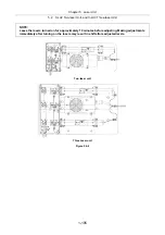
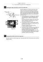
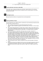
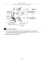
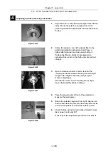
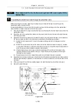
Adjusting the angle of the dichroic mirror for the He-Ne laser
Figure 5.2-11
Mount the dichroic mirror centering tool in place of the
dichroic mirror for the argon laser again. Change the
direction of the centering tool and adjust the angle of the
dichroic mirror for the He-Ne laser located at the far side
from the argon laser. (See Figure 5.2-11.) Align the beam
of the He-Ne laser with the Hole R on the centering tool.
(See Figure 5.2-7.)
1.
For horizontal adjustment, slightly loosen hexagonal
socket-head bolts a1, insert a screwdriver or thin
stick into a2 to permit tilting, then rotate the entire
mirror.
For vertical adjustment, slightly loosen setscrews b1,
insert a screwdriver or thin stick into b2 to permit
tilting, then rotate the entire mirror.
2.
When the dichroic mirror is properly angled, tighten
hexagonal socket-head bolts a1 and setscrews b1 to
secure the mirror in place.
(Simultaneous tightening of the two screws
minimizes positional deviation.)
3.
Adjust the accuracy of the dichroic mirror angle within
±
0.2 mm from centering tool hole R. (Make the
adjustment carefully, to ensure smooth entry of the
laser beam into the optical-fiber cable.)
For the three-laser unit, the adjustment of the dichroic
mirror for the He-Ne1 laser will be made in the final
adjustment , rather than at this step.
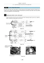
5
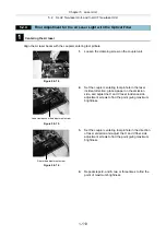
Setting up the dichroic mirror for the argon laser
Mount the dichroic mirror for the argon laser on the argon laser section. This dichroic mirror has a blue
reflection surface.
Hexagonal socket-
head bolts a1
a2
a1
b1
b2
Setscrews b1
a2
b2
Summary of Contents for Eclipse Ti Series
Page 2: ......
Page 14: ......
Page 256: ......
Page 258: ......
Page 260: ...Contents 2 2 8 2 Environmental Conditions 2 70 8 3 Safety Standards Compliance 2 71 ...

