1-213
Connection between the Laser Unit and the Microscope
6
6.1
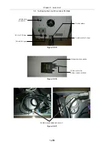
Setting and Connecting the TI-LUSU Shutter Unit
RS-232C
LASER UNIT
TI-LUSU
INPUT
1A
POWER
SAFETY
COVER
CLOSE
BINO
CLOSE
12V
LASER SHUTTER
Exclusive use for TI-TIRF system
Don't use this unit with other systems.
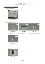
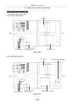
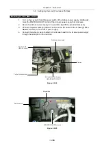
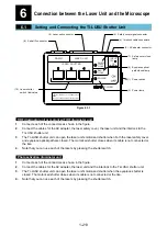
Figure 6.1-1
TIRF illuminator unit or motorized TIRF illuminator unit
1.
Connect each of the connectors as shown in the figure.
2.
Connect the cables for the AC adapter, the laser safety cover, the laser unit and the interlock to the
TI-LUSU shutter unit.
3.
The TI-LUSU shutter unit can open the laser unit’s motorized shutter when both the laser safety cover
and eyepiece optical path are closed. The motorized shutter closes when its cable is not connected or
the like.
4.
Note that you can use each of the lasers by pressing the shutter switch.
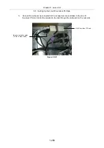
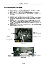
Photo activation illuminator unit
1.
Connect each of the connectors as shown in the figure.
2.
Connect the cables for the AC adapter, the laser unit and the interlock to the TI-LUSU shutter unit.
3.
The TI-LUSU shutter unit can open the laser unit’s motorized shutter when the eyepiece shutter is
closed. The motorized shutter closes when its cable is not connected or the like.
4.
Note that you can use each of the lasers by pressing the shutter switch.
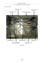
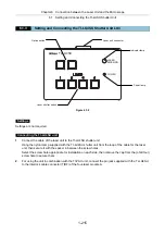
(9) Serial IF connector
(8) Laser unit connector
(2) Power lamp
(1) Power switch
(5) Eyepiece optical
path closed lamp
(7) Safety cover close
lamp
(3) AC adapter connector
(4) Interlock cable connectors
(6) Safety cover signal connector
(10) Laser shutter
switch / indicators
Summary of Contents for Eclipse Ti Series
Page 2: ......
Page 14: ......
Page 256: ......
Page 258: ......
Page 260: ...Contents 2 2 8 2 Environmental Conditions 2 70 8 3 Safety Standards Compliance 2 71 ...

