


Chapter 5 Laser Unit
5.3 C-LU3EX Three-laser Unit EX
1-152
5.3.6
Final Adjustment for the He-Ne Laser Light and 405 Laser Light with the
Optical Fiber
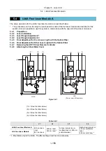
The procedure given below describes how to transmit laser light through the fiber by adjusting the dichroic
mirror adjustment unit and beam shift unit alone, without using the coupler.
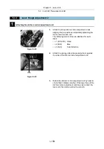
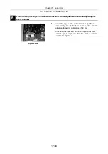
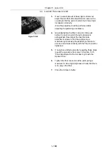
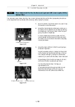
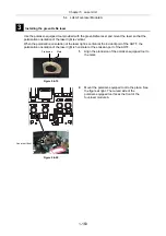
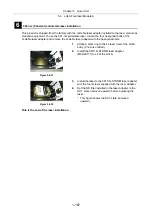
1.
Open the shutter only for the laser to be used. Close
the shutters on the other lasers.
Figure 5.3-71
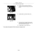
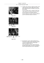
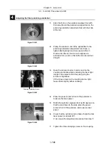
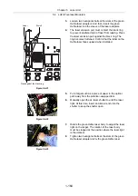
2.
Adjust the horizontal and vertical axis setscrews on
the dichroic mirror adjustment unit while monitoring
the brightness on the power meter to find the point
giving a maximum brightness.
To reduce tightening deviations, tighten the two
horizontal axis clamp screws to the point at which
the dichroic mirror is able to rotate before adjusting
horizontal rotation.
Figure 5.3-72
Figure 5.3-73
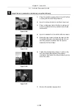
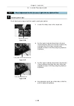
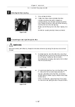
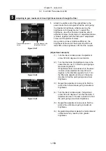
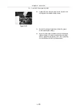
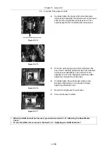
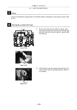
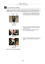
3.
Adjust the beam shift unit to find the point giving a
maximum brightness.
Adjust horizontally either by rotating the beam shift
unit by hand or by inserting an Allen key in the tool
hole. Adjust vertically by moving the vertical axis
setscrew up or down with the clamp screw loosened.
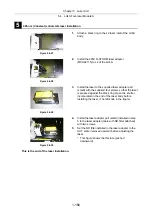
Approximately 45% should be achieved in front of
and behind the fiber coupling for each laser.
For the 405 cylindrical laser, this figure is
approximately 10%.
(Transmitting the light through the AOM unit will
distort the beam shape and result in a lower
transmission ratio than without the AOM unit.)
Horizontal axis clamp screws
Tool hole
Vertical axis clamp screw
Vertical axis setscrew
Summary of Contents for Eclipse Ti Series
Page 2: ......
Page 14: ......
Page 256: ......
Page 258: ......
Page 260: ...Contents 2 2 8 2 Environmental Conditions 2 70 8 3 Safety Standards Compliance 2 71 ...


