Chapter 1 System Configurations and Part Names
1.4 Name of Each Part
2-20
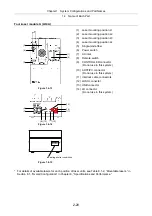
Four-laser module A (LU4A)
Figure 1.4-13
Figure 1.4-14
L4
L3
L2
L1
POWER
Figure 1.4-15
(1) Laser mounting position L1
(2) Laser mounting position L2
(3) Laser mounting position L3
(4) Laser mounting position L4
(5) Single-mode
fiber
(6) Power
switch
(7) AC
inlet
(8) Remote
switch
(9) CONTROLLER
connector
(Do not use in this system.)
(10) AOTF/PC connector
(Do not use in this system.)
(11) Interlock cable connectors
(12) LUSU connector
(13) USB connector
(14) LD connector
(Do not use in this system.)
* For details of available lasers for each position of laser units, see Table 8.1-2, “Mountable lasers,” in
Section 8.1, “Overall Configuration” in Chapter 8, “Specifications and Performance.”
(3)
(5)
(1)
(4)
(2)
(6)
(12)
(8)
(13)
(14)
(7)
(11)
(9)
(10)
Indicating shutter conditions
Summary of Contents for Eclipse Ti Series
Page 2: ......
Page 14: ......
Page 256: ......
Page 258: ......
Page 260: ...Contents 2 2 8 2 Environmental Conditions 2 70 8 3 Safety Standards Compliance 2 71 ...

