


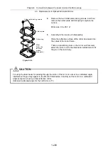

Chapter 6 Connection between the Laser Unit and the Microscope
6.1 Setting and Connecting the TI-LUSU Shutter Unit
1-215
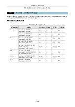
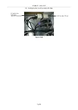
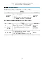
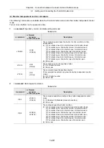
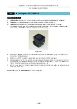
6.1.3
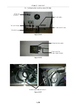
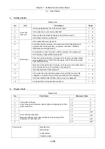
Setting and Connecting the TI-LU4SU Shutter Unit LU4
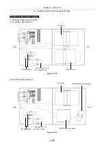
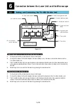
POWER
TI-LU4SU
EMISSION
LASER
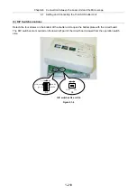
Figure 6.1-2
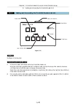
Settings
Settings are not required.
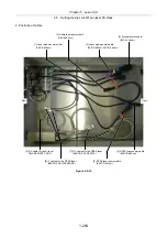
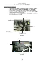
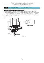
Connecting the TI-LU4SU unit
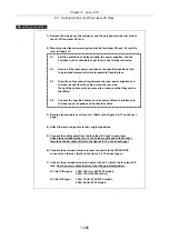
1.
Connect the cable of the laser unit to the TI-LU4SU shutter unit.
Hang the nylon clamp supplied with the TI-LU4SU shutter unit from the loop of the cable for the laser
unit, then secure it with the spacer in between the screw holes.
Select the screw hole appropriate for installation on each side, then remove the cap from the (of all four)
screw hole to secure them.
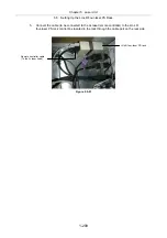
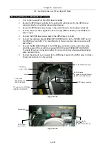
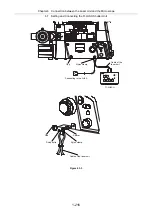
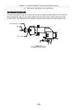
2.
For using the unit in combination with the TI-PAU unit, connect the pin jack supplied with the TI-LU4SU
to the interlock cable connector (TIRF) of the four-laser module A.
Indicator lamp
Option switch
Laser shutter switch
Power lamp
Laser unit connector
Summary of Contents for Eclipse Ti Series
Page 2: ......
Page 14: ......
Page 256: ......
Page 258: ......
Page 260: ...Contents 2 2 8 2 Environmental Conditions 2 70 8 3 Safety Standards Compliance 2 71 ...


