


Chapter 5 Laser Unit
5.2 C-LU2 Two-laser Unit, and C-LU3 Three-laser Unit
1-113
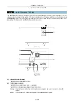
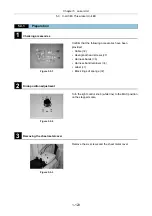
5.2.4
Final Adjustment for the Ar Laser Light with the Optical Fiber
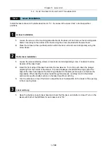
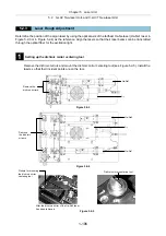
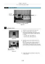
1
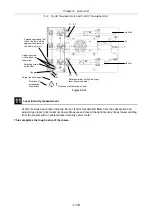
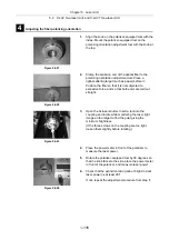
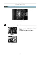
Centering the Ar laser
Align the Ar laser beam with the coupler centering tool pinhole.
Figure 5.2-14
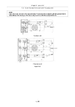
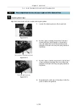
1.
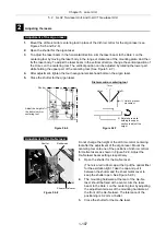
Loosen the clamping screw on the coupler unit.
Figure 5.2-15
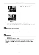
2.
Set the coupler centering tool pinhole in the laser
incident direction, place a paper on the emission
side, and adjust the H and V laser incidence side
adjustment screws to find the point giving maximum
brightness.
Figure 5.2-16
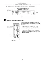
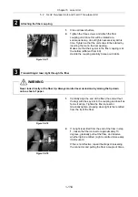
3.
Set the coupler centering tool pinhole in the direction
of laser emission and adjust the H and V fiber side
adjustment screws to find the point giving maximum
brightness.
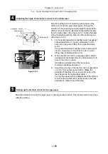
4.
Repeat
steps
2.
and
3.
two or three times to find the
point of maximum brightness.
Laser incidence side adjustment screw
Fiber side adjustment screw
Summary of Contents for Eclipse Ti Series
Page 2: ......
Page 14: ......
Page 256: ......
Page 258: ......
Page 260: ...Contents 2 2 8 2 Environmental Conditions 2 70 8 3 Safety Standards Compliance 2 71 ...


