


Digitax HD M753 Control User Guide
49
Issue Number: 3
Use Pr
00.005
to select the required frequency/speed reference as
follows:
Pr
00.006
limits the maximum output current of the drive (and hence
maximum motor torque) to protect the drive and motor from overload.
Set Pr
00.006
at the required maximum torque as a percentage of the
rated torque of the motor, as follows:
(%)
Where:
T
R
Required maximum torque
T
RATED
Motor rated torque
Alternatively, set Pr
00.006
at the required maximum active (torque-
producing) current as a percentage of the rated active current of the
motor, as follows:
(%)
Where:
I
R
Required maximum active current
I
RATED
Motor rated active current
6.4.4 Voltage boost, (open-loop), Speed-loop PID
gains (RFC-A / RFC-S)
Open-loop
There are six voltage modes available, which fall into two categories,
vector control and fixed boost. For further details, refer to ???section
Pr 00.007 {05.014} Open Loop Control Mode
RFC-A/ RFC-S
Pr
00.007
(
03.010
) operates in the feed-forward path of the speed-
control loop in the drive. See Figure 12-4 on page 156 for a schematic of
the speed controller. For information on setting up the speed controller
gains, refer to Chapter 8
Open-loop
When
Open-loop Control Mode
(00.007) is set at
Fd
or
SrE
, set
Pr
00.008
(
05.015
) at the required value for the motor to run reliably at
low speeds.
Excessive values of Pr
00.008
can cause the motor to be overheated.
RFC-A/ RFC-S
Pr
00.008
(
03.011
) operates in the feed-forward path of the speed-
control loop in the drive. See Figure 12-4 on page 156 for a schematic of
the speed controller. For information on setting up the speed controller
gains, refer to Chapter 8
Open-loop
Set Pr
00.009
(
05.013
) at 0 when the V/f characteristic applied to the
motor is to be fixed. It is then based on the rated voltage and frequency
of the motor.
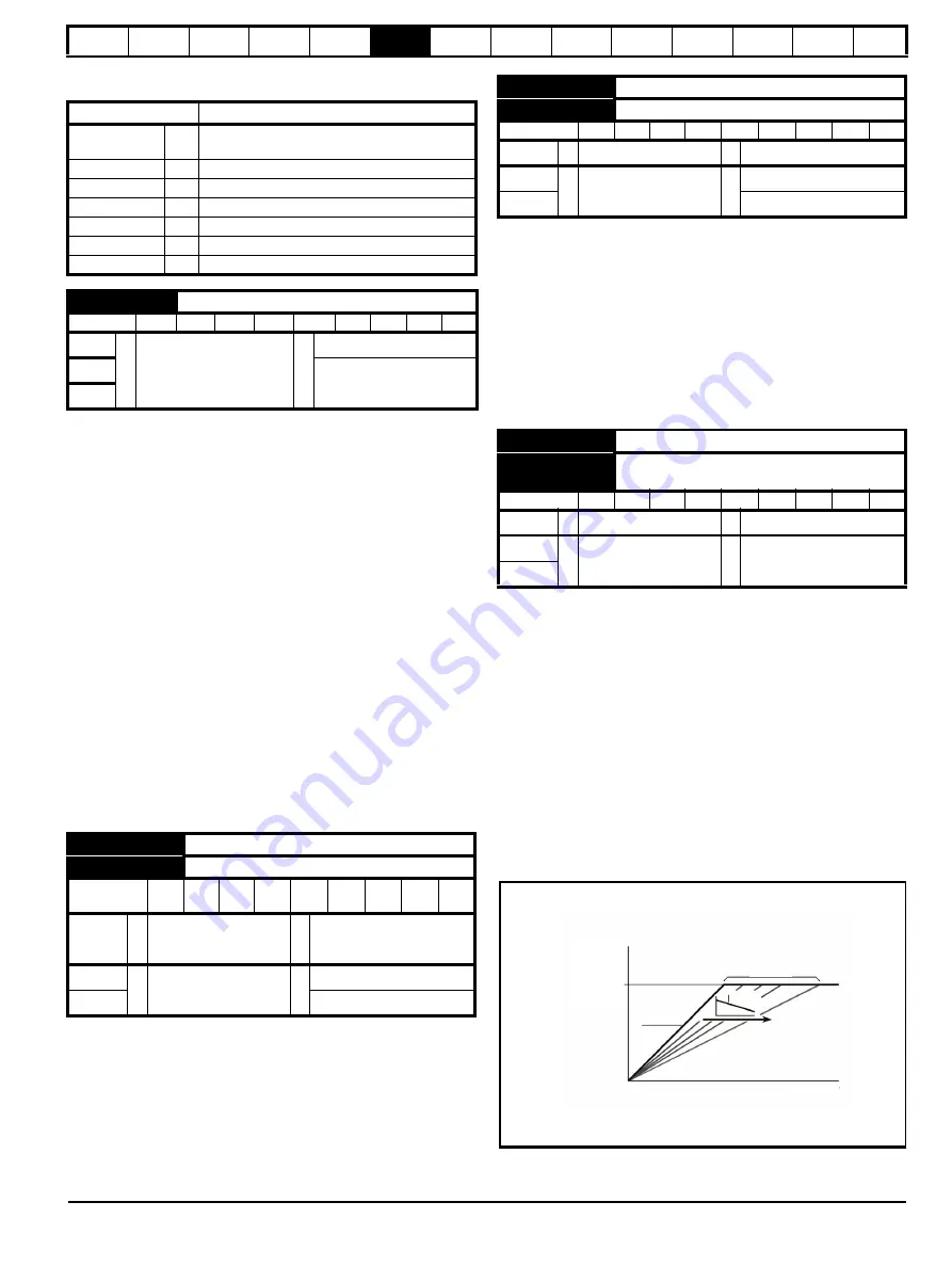
Set Pr
00.009
at 1 when reduced power dissipation is required in the
motor when it is lightly loaded. The V/f characteristic is then variable
resulting in the motor voltage being proportionally reduced for lower
motor currents. Figure 6-2 shows the change in V/f slope when the
motor current is reduced.
RFC-A / RFC-S
Pr
00.009
(
03.012
) operates in the feedback path of the speed-control
loop in the drive. See Figure 12-4
Menu 3 RFC-A, RFC-S logic diagram
on page 156 for a schematic of the speed controller. For information on
setting up the speed controller gains, refer to Chapter 8
Figure 6-2 Fixed and variable V/f characteristics
Setting
Description
A1 A2
0
Analog input 1 OR analog input 2 selectable by
digital input, terminal 28
A1 Preset
1
Analog input 1 OR preset frequency/speed
A2 Preset
2
Analog input 2 OR preset frequency/speed
Preset (3)
3
Pre-set frequency/speed
Keypad (4)
4
Keypad mode
Precision (5)
5
Precision reference
Keypad Ref (6)
6
Keypad Reference
00.006 {04.007}
Symmetrical Current Limit
RW
Num
US
OL
0.0 to VM_MOTOR1_
CURRENT_LIMIT %
165 %
RFC-A
250 %
RFC-S
00.007 {05.014}
Open-loop Control Mode (OL)
00.007 {03.010}
Speed Controller Proportional Gain Kp1 (RFC)
RW
Txt /
Num
US
OL
Ur S (0), Ur (1),
Fixed (2), Ur Auto (3),
Ur I (4), Square (5)
Ur I (4)
RFC-A
0.0000 to 200.000 s/rad
0.0300 s/rad
RFC-S
0.0100 s/rad
00.006
T
R
T
RATED
--------------------
100
=
00.006
I
R
I
RATED
-------------------
100
=
00.008 {05.015}
Low Frequency Voltage Boost (OL)
00.008 {03.011}
Speed Controller Integral Gain Ki1 (RFC)
RW
Num
US
OL
0.0 to 25.0 %
1.0 %
RFC-A
0.00 to 655.35 s
2
/rad
0.10 s
2
/rad
RFC-S
1.00 s
2
/rad
00.009 {05.013}
Dynamic V to F Select (OL)
00.009 {03.012}
Speed Controller Differential Feedback Gain
Kd 1 (RFC)
RW
Bit
US
OL
Off (0) or On (1)
Off (0)
RFC-A
0.00000 to
0.65535 1/rad
0.00000 1/rad
RFC-S
Motor
voltage
AC supply
voltage
Frequency
MOTOR
0.09 = 1
0.09 = 0
Summary of Contents for Digitax HD M753 EtherCAT
Page 261: ......
Page 262: ...0478 0461 03...