


Digitax HD M753 Control User Guide
111
Issue Number: 3
Table 9-60 Touch probe source
The touch probe source can be defined with the following values:
Table 9-61 Touch probe 1 positive edge
Table 9-62 Touch probe 1 negative edge
The Touch Probe Status (0x60B9), Touch probe 1 positive edge
(0x60BA) and Touch probe 1 negative (0x60BB) objects will be updated
every 250
μ
s, and it will be possible to include them in TxPDOs.
The enable touch probe 1 (bit 0), enable positive edge sampling (bit 4)
and enable negative edge sampling (bit 5) of the Touch probe function
(0x60B8) objects will be read and acted upon every 250
μ
s.
The other bits of the touch probe function object and the touch probe
source object 0x60D0 which are used for touch probe configuration
(i.e. trigger source, trigger mode) will be acted up on in the background.
However the touch probe configuration will not manipulate the drive
freeze system until first time enabled, this is to make sure customer
configuration for the drive freeze system will not be changed if they are
not using touch probe. After drive system first been configured, the new
touch probe configuration will take effect when the CANopen state
machine leaves operating states (i.e. operation-enabled and quick-stop-
active).
It will be possible to include touch probe function object 0x60B8 in the
RxPDOs. The touch probe source (0x60D0) object can only be
accessed by SDO.
9.18.15.2
Trigger mode of touch probe
There are two trigger modes that can be configured via trigger mode
(bit 1) of the touch probe function object (0x60B8):
•
Trigger first event: this mode captures the position and set the
position stored bit when the first event of the trigger source occurs.
The further events won’t be captured until the enable bit(s) is cleared
and reset.
•
Continuous: this mode captures the position each time an event
occurs from the trigger source.
The position stored bit will only set for the first trigger, no further
indication when additional events occur. The value in the stored position
object(s) will reflect the most recent record. The position stored bit will be
cleared once the associate enable bit is cleared, however the stored
position will retain.
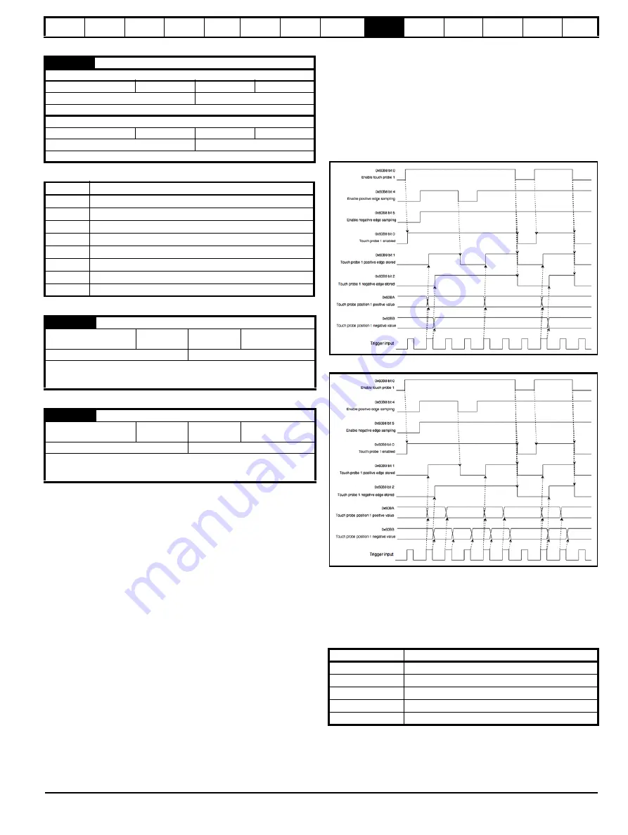
Here are two example timing diagrams, to explain the operation
sequence of the touch probe function:
Figure 9-7 Trigger first event
(0x60B8 bit1 = 0)
Figure 9-8 Continuous
(0x60B8 bit1 = 1)
9.18.16 Basic position control
Basic position control is supported in RFC-A and RFC-S modes.
The position control described here is used under the interpolated
position mode of operation. Table 9-63 lists the objects that are
supported:
Table 9-63 Basic position control supported objects
0x60D0
Touch probe source
Sub-index 0
Access: RO
Range: N/A
Size: 1 byte
Unit: N/A
Default: 1
Type:
USINT
Description:
The number of the highest sub-index of this object
Sub-index 1
Access: RW
1 to 5
Size: 2 bytes
Unit: N/A
Default: 1
Type:
INT
Description:
Touch probe 1 source
Value
Definition
1
Drive digital input 4
2
Drive digital input 5
3
Not supported
4
Not supported
5
Hardware zero impulse signal of position encoder
6
Software zero impulse signal of position encoder
-1
P1 marker
-2
P2 marker
0x60BA
Touch probe 1 positive edge
Access: RO
Range: N/A
Size: 4 bytes
Unit: User-defined
position units
Default: 0
Type:
DINT
Description:
This will contain a position value frozen when a positive edge
occurred on the touch probe 1 input. The value will only be valid
when the positive position stored bit is set.
0x60BB
Touch probe 1 negative edge
Access: RO
Range: N/A
Size: 4 bytes
Unit: User-defined
position units
Default: 0
Type:
DINT
Description:
This will contain a position value frozen when a negative edge
occurred on the touch probe 1 input. The value will only be valid
when the negative position stored bit is set.
Index
Name
0x6062
position_demand_value
0x6065
following_error_window
0x6067
position_window
0x60F4
following_error_actual_value
0x60FB
position_control_parameter_set
Summary of Contents for Digitax HD M753 EtherCAT
Page 261: ......
Page 262: ...0478 0461 03...