


242
Digitax HD M753 Control User Guide
Issue Number: 3
Over Speed
Motor speed has exceeded the over speed threshold
7
In open loop mode, if the
Output Frequency
(05.001) exceeds the threshold set in
Over Speed Threshold
(03.008) in either
direction an
Over Speed
trip is produced. In RFC-A and RFC-S mode, if the Speed Feedback (03.002) exceeds the
Over Speed Threshold
in Pr
03.008
in either direction an
Over Speed
trip is produced. If Pr
03.008
is set to 0.0 the
threshold is then equal to 1.2 x the value set in Pr
01.006
.
In RFC-A and RFC-S mode, if an SSI encoder is being used and Pr
03.047
is set to 0 an
Over Speed
trip will be produced
when the encoder passes through the boundary between its maximum position and zero.
Recommended actions:
•
Check the motor is not being driven by another part of the system
•
Reduce the
Speed Controller Proportional Gain
(03.010) to reduce the speed overshoot (RFC-A, RFC-S modes only)
•
If an SSI encoder is being used set Pr
03.047
to 1
The above description relates to a standard Over Speed trip, however in RFC-S mode it is possible to produce an
Over
Speed.1
trip. This is caused if the speed is allowed to exceed the safe level in RFC-S mode with flux weakening when
Enable High Speed Mode
(05.022) is set to -1.
Over Volts
DC bus voltage has exceeded the peak level or maximum continuous level for 15 seconds
2
The
Over Volts
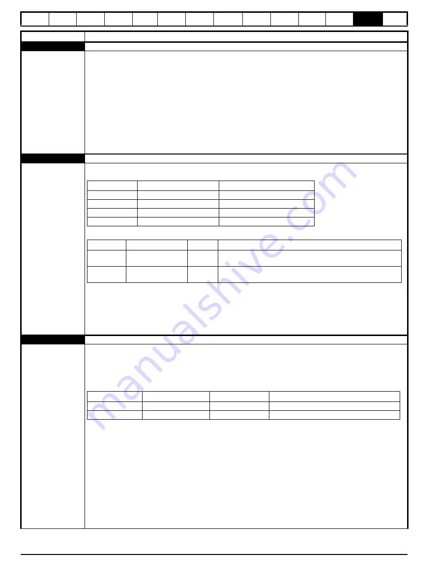
trip indicates that the DC bus voltage has exceeded the VM_DC_VOLTAGE[MAX] or
VM_DC_VOLTAGE_SET[MAX] for 15 s. The trip threshold varies depending on voltage rating of the drive as shown below.
Sub-trip Identification
Recommended actions:
•
Increase deceleration ramp (Pr
00.004
)
•
Decrease the braking resistor value (staying above the minimum value)
•
Check nominal AC supply level
•
Check for supply disturbances which could cause the DC bus to rise
•
Check motor insulation using an insulation tester
Phase Loss
Supply phase loss
32
The Phase Loss trip indicates that the drive has detected an input phase loss or large supply imbalance. Phase loss can be
detected directly from the supply where the drive has a thyristor base charge system (Frame size 8 and above). If phase
loss is detected using this method the drive trips immediately and the xx part of the sub-trip is set to 01. In all sizes of drive
phase loss is also detected by monitoring the ripple in the DC bus voltage in which case the drive attempts to stop the drive
before tripping unless bit 2 of
Action On Trip Detection
(10.037) is set to one. When phase loss is detected by monitoring
the ripple in the DC bus voltage the xx part of the sub-trip is zero.
(1) Input phase loss detection can be disabled when the drive required to operate from the DC supply or from a single
phase supply in
Input Phase Loss Detection Mode
(06.047).
(2) For a parallel power-module system the rectifier number will be one as it is not possible to determine which rectifier has
detected the fault.
This trip does not occur in regen mode.
Recommended actions:
•
Check the AC supply voltage balance and level at full load
•
Check the DC bus ripple level with an isolated oscilloscope
•
Check the output current stability
•
Check for mechanical resonance with the load
•
Reduce the duty cycle
•
Reduce the motor load
•
Disable the phase loss detection, set Pr
06.047
to 2.
Trip
Diagnosis
Voltage rating
VM_DC_VOLTAGE[MAX]
VM_DC_VOLTAGE_SET[MAX]
200
415
410
400
830
815
575
990
970
690
1190
1175
Source
xx
y
zz
Control
system
00
0
01: Instantaneous trip when the DC bus voltage exceeds
VM_DC_VOLTAGE[MAX].
Control
system
00
0
02: Time delayed trip indicating that the DC bus voltage is above
VM_DC_VOLTAGE_SET[MAX].
Source
xx
y
zz
Control system
00
0
00: Phase loss detected from DC bus ripple
Power system (1)
Power module number
Rectifier number (2) 00: Phase loss detected directly from the supply
Summary of Contents for Digitax HD M753 EtherCAT
Page 261: ......
Page 262: ...0478 0461 03...