


5 Menu tree
5.5 MAIN MENU – Positioning
FST-2_HB.EN12/05
129
Cal-Results –
UP–Speed
Upward speeds measured during the calibration drive for all
drive speeds V1 .. VI.
-10000 .. 10000 mm/s
Cal-Results –
UP–Accel.
Upward acceleration distances measured during the
calibration drive for all drive speeds V1 .. VI.
0 .. 50000 mm
Cal-Results –
UP–Decel.
Upward deceleration distances measured during the
calibration drive for all drive speeds V1 .. VI.
0 .. 50000 mm
Cal-Results –
UP–t_Accel.
Upward acceleration times measured during the calibration
drive for all drive speeds V1 .. VI.
0 .. 32767 msec
Cal-Results –
UP–t_Decel.
Upward deceleration times measured during the calibration
drive for all drive speeds V1 .. VI.
0 .. 32767 msec
Cal-Results –
DOWN–Speed
Downward speeds measured during the calibration drive for
all drive speeds V1 .. VI.
-1000 .. 10000 mm/s
Cal-Results –
DOWN–Accel.
Downward acceleration distances measured during the
calibration drive for all drive speeds V1 .. VI.
0 .. 50000 mm
Cal-Results –
DOWN–Decel.
Downward deceleration distances measured during the
calibration drive for all drive speeds V1 .. VI.
0 .. 50000 mm
Cal-Results –
DOWN–t_Accel.
Downward acceleration times measured during the calibration
drive for all drive speeds V1 .. VI.
0 .. 32767 msec
Cal-Results –
DOWN–t_Decel.
Downward deceleration times measured during the calibration
drive for all drive speeds V1 .. VI.
0 .. 32767 msec
Cal-Results –
V80%–SpeedMon
Speed monitoring point for deceleration monitoring when
approaching the levelling position of the top or bottom landing.
0 .. 10000 mm
Cal-Results –
V80%–Distance
Speed monitoring point for deceleration monitoring when
approaching the levelling position of the top or bottom landing.
0 .. 49999 mm
Pseudo floors –
Pos. (Rel.)
Additional stops without shaft doors. “Pseudo floors” are
additional floors without call signals or doors. They can only be
approached using the programmable inputs/outputs and are
used for example as locking position for cable lifts without
machine compartment or parking floor between regular floors
(see “Function “special drive”” on page 166).
0 .. 49999 mm
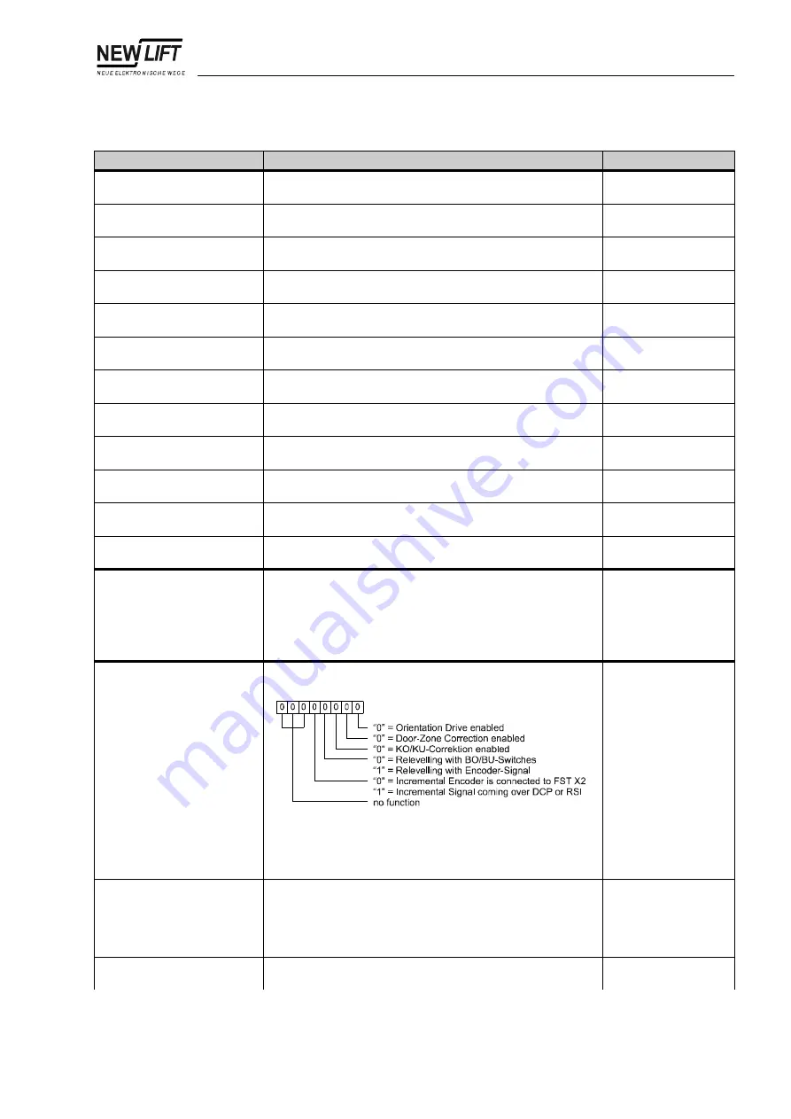
Increm. Positng. –
Control
Control register for incremental positioning:
Default setting for this parameter:
00001000
Only change this setting after consulting NEW LIFT!
00000000 ..
11111111
Increm. Positng. –
Auto-Orien.
With incremental positioning, an orientation drive to the top or
bottom landing is required after switching the controller on and
off (also after a power failure). The orientation drive is started
automatically after switching on the FST-2-Controller. Only
change this parameter after consulting NEW LIFT!
YES
NO
Increm. Positng. –
Orien. delay
Delay of the orientation drive after switching on the FST-2-
Controller.
0 .. 9999 ms
Menu item
Description
Setting range
Summary of Contents for FST-2
Page 6: ...Table of contents 4 FST 2_HB EN12 05...
Page 98: ...5 Menu tree 5 1 General 96 FST 2_HB EN12 05 Fig 5 1 FST 2 Controller menu tree part 1...
Page 99: ...5 Menu tree 5 1 General FST 2_HB EN12 05 97 Fig 5 2 FST 2 Controller menu tree part 2...
Page 100: ...5 Menu tree 5 1 General 98 FST 2_HB EN12 05 Fig 5 3 FST 2 Controller menu tree part 3...
Page 101: ...5 Menu tree 5 1 General FST 2_HB EN12 05 99 Fig 5 4 FST 2 Controller menu tree part 4...
Page 102: ...5 Menu tree 5 1 General 100 FST 2_HB EN12 05 Fig 5 5 FST 2 Controller menu tree part 5...
Page 103: ...5 Menu tree 5 1 General FST 2_HB EN12 05 101 Fig 5 6 FST 2 Controller menu tree part 6...
Page 104: ...5 Menu tree 5 1 General 102 FST 2_HB EN12 05 Fig 5 7 FST 2 Controller menu tree part 7...
Page 105: ...5 Menu tree 5 1 General FST 2_HB EN12 05 103 Fig 5 8 FST 2 Controller menu tree part 8...
Page 174: ...6 Programmable inputs and outputs 172 FST 2_HB EN12 05...