Max 8/16 and T1/E1 User’s Guide – Chapter 1
Page 4
2. Install the Max 8/16 or T1/E1 unit and connect the cabling.
3. Configure the LAN settings on the Max 8/16 or T1/E1 so that
it communicates with your LAN.
4. Log into the Max 8/16 or T1/E1 Web manager.
5. Finish configuring your FXS ports via the Web Manager.
6. Test your installation by making an Internet telephone call.
Locating Your FXS and FXO Ports
You need to be able to identify the Max’s ports before you can begin
configuring its LAN settings. After the LAN settings are configured,
the Max Web Manager will identify the Max’s ports. But before the
Web Manager is available, if you do not already know which ports are
present and where they are located, you can identify your ports by
physically inspecting the Max’s AVU (Analog Voice Unit) cards.
AVU cards are removable boards that contain the port interface cards
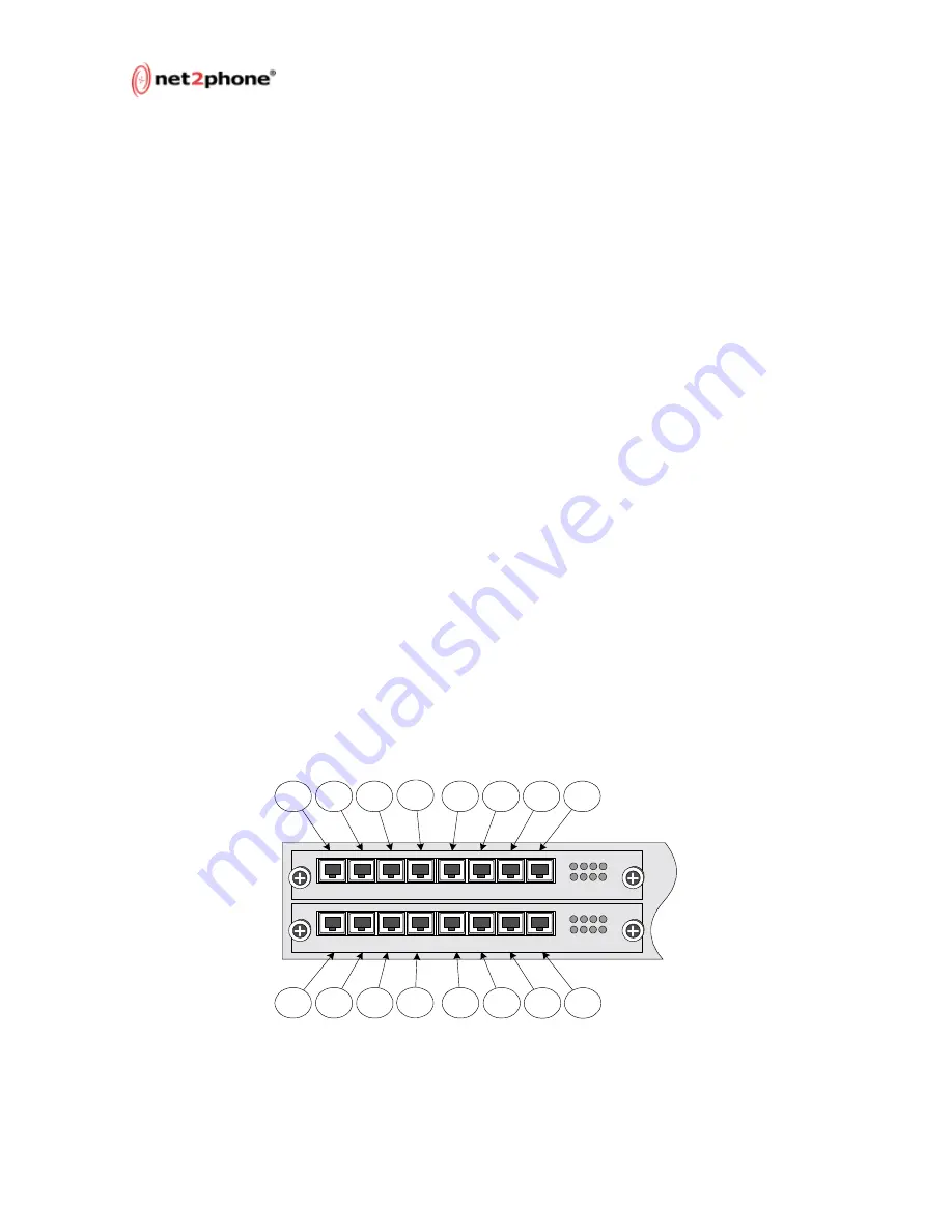
whose RJ-11 ports are visible on the Max’s rear panel. Figure 1,
below, shows the rear panel of a Max with two AVU cards installed,
each containing eight ports.
This section will explain how to remove the cards to conduct an
inspection, and how to differentiate between the port interface types.
Again, this process is only required once, before the Max’s LAN
settings are configured.
Physical Port Numbering
Figure 1 illustrates the physical port numbering on the Max’s rear
panel for a unit with 16 ports installed. (Your unit may only have
eight ports.) The Max Web Manager references these numbers when
identifying ports, setting up the Max’s features and configuring
Net2Phone calling accounts.
AVU
1 2 3 4
5 6 7 8
1
2
3
4
5
6
7
8
AVU
1 2 3 4
5 6 7 8
1
2
3
4
5
6
7
8
Port
1
Port
2
Port
4
Port
5
Port
6
Port
7
Port
8
Port
11
Port
9
Port
10
Port
12
Port
13
Port
14
Port
15
Port
16
Port
3
Figure 1 – Physical Port Numbers on the Max’s Rear Panel
As the illustration shows, the ports are numbered from upper left to
lower right. In the top row, the left-most port is port number 1 and


