3-44 Windows Setup and Operation
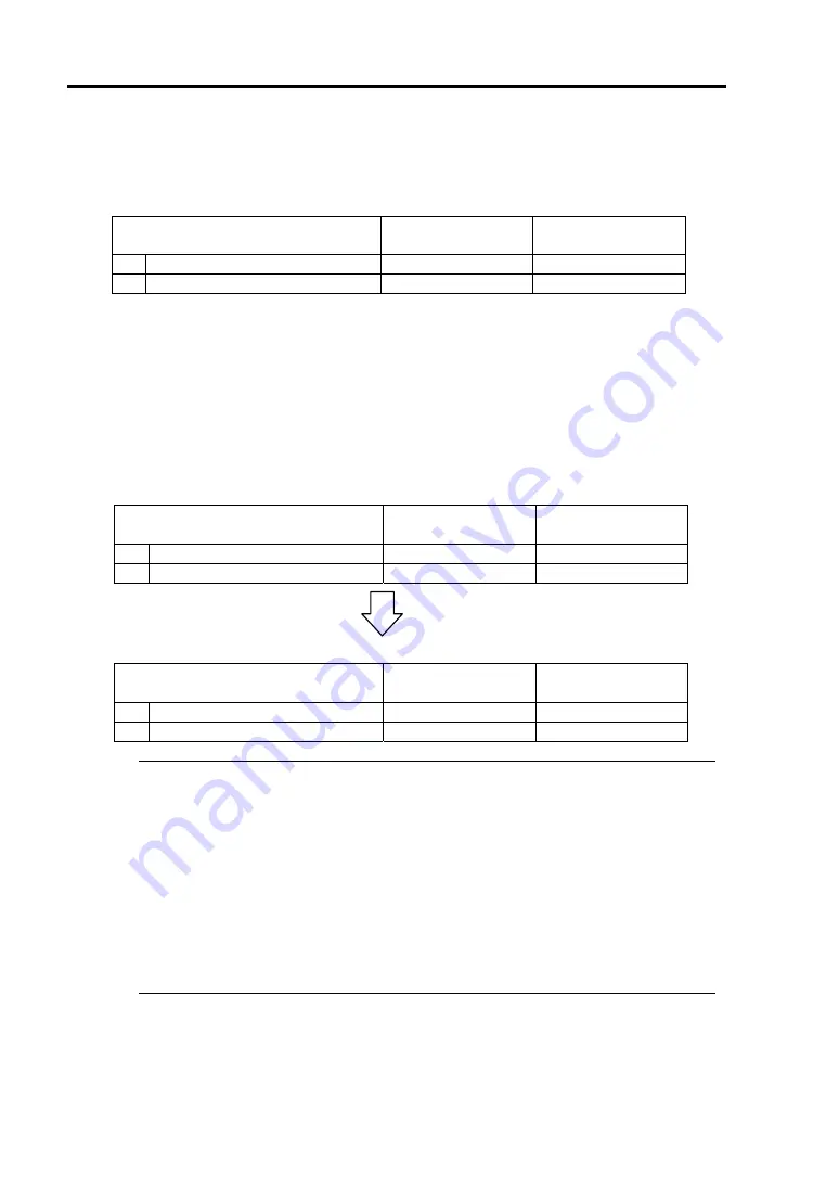
When you stop the operation of a CPU module, the indications of the status LEDs change as
follows. Below denotes that the only one CPU module is operating.
[Indications of status LEDs]
LED
CPU module#1
(Stopped)*
CPU module#2
(Operating)
1
CPU module status LED1
Red
-
2
CPU module status LED2
-
Amber
* As an example, the indications of when CPU module#1 is stopped are shown.
3.
Press the start button of the CPU module stopped by ft server utility.
In the ft server utility, select the stopped CPU module and click [Up] of [Bring Up/Bring
Down].
Once the CPU module is started, hardware diagnosis and then synchronization of memory
(memory copy) are performed, and the duplication process is completed.
Note that the system is paused temporarily for copying memory during memory
synchronization.
[Indications of status LEDs during diagnosis]
LED
CPU module#1
(Started)
CPU module#2
(Operating)
1
CPU module status LED1
Red
-
2
CPU module status LED2
Green
Amber
[Indications of status LEDs after completion of duplication]
LED
CPU module#1
(Operating)
CPU module#2
(Operating)
1
CPU module status LED1
-
-
2
CPU module status LED2
Green
Green
IMPORTANT:
After duplication is completed, the status of memory will be checked.
Wait until this process ends to perform the next step (evaluation of start and stop of PCI
and CPU modules). When the process is complete, the following event log will be
output:
Source: srabid
Type: Information
Event ID:
4137
Description: Memory consistency check has completed memory scan.
Summary of Contents for Express5800/340Hb-R N8800-047F
Page 1: ...N8800 047F 073F NEC Express5800 340Hb R User s Guide 1st Edition 3 2005 856 125126 901 A ...
Page 14: ...viii This page is intentionally left blank ...
Page 17: ...Precautions for Use 1 3 Label A Label B Label C Label D ...
Page 20: ...1 6 Precautions for Use Label A Label B Label C ...
Page 22: ...1 8 Precautions for Use Label A Label B Label C ...
Page 51: ...General Description 2 15 Chassis Board Layout Clock board Interface board Back panel ...
Page 76: ...2 40 General Description This page is intentionally left blank ...
Page 90: ...3 14 Windows Setup and Operation 7 Configure the mirror of the extended volume ...
Page 124: ...3 48 Windows Setup and Operation This page is intentionally left blank ...
Page 158: ...4 34 System Configuration This page is intentionally left blank ...
Page 171: ...Installing and Using Utilities 5 13 ...
Page 244: ...6 12 Maintenance This page is intentionally left blank ...
Page 278: ...7 34 Troubleshooting This page is intentionally left blank ...
Page 306: ...8 28 Option This page is intentionally left blank ...
Page 312: ...B 4 IRQ and I O Port Address This page is intentionally left blank ...


