6 Functions and settings
Maschinenfabrik Reinhausen GmbH 2016
154
5163667/00 EN
TRAFOGUARD® ISM®
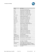
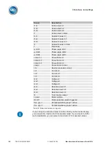
Signal
Description
P L1
Active power L1
P L2
Active power L2
P L3
Active power L2
P
Active power in total
S L1
Apparent power L1
S L2
Apparent power L2
S L3
Apparent power L3
S
Apparent power in total
f
Frequency
φ U1/I1
Phase angle U1/I1
φ U2/I2
Phase angle U2/I2
φ U3/I3
Phase angle U3/I3
cos(φ) L1
Power factor L1
cos(φ) L2
Power factor L2
cos(φ) L3
Power factor L3
cos(φ)
Power factor in total
I N
Neutral conductor current
I L1
Current L1
I L2
Current L2
I L3
Current L3
U L1
Voltage L1
U L2
Voltage L2
U L3
Voltage L3
Q L1
Reactive power L1
Q L2
Reactive power L2
Q L3
Reactive power L3
Q
Total reactive power
t motor
Motor runtime
Q1 Off
Motor protective switch triggered
Par. grp. 1
Parallel operation group 1 active
Par. grp. 2
Parallel operation group 2 active
Table 35: Measured values and signals
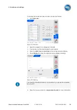
If you call up the measured value recorder directly on the device display,
you can select a maximum of 3 measured values. If you access it via the
web visualization, you can select a maximum of 10 measured values.
Summary of Contents for TRAFOGUARD ISM
Page 1: ...Monitoring System TRAFOGUARD ISM Operating Instructions 5163667 00 EN ...
Page 222: ......
Page 223: ......

