
4 Mounting
Maschinenfabrik Reinhausen GmbH 2016
53
5163667/00 EN
TRAFOGUARD® ISM®
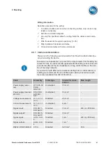
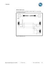
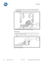
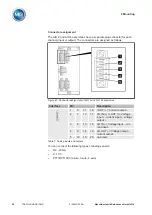
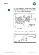
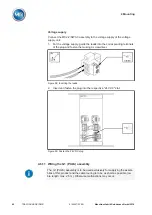
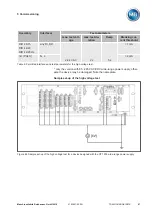
0/4...20 mA-Sensor
You must connect a 4...20 mA sensor to the pins
and
. You must also
connect the supplied bridge to the pins
,
, and
.
I OUT (+)
I/U IN (+)
U OUT (+)
I/U IN (-)
I/U OUT (+)
1
2
3
4
5
---
4...20 mA signal source
Figure 44: Connection example for a 4...20 mA sensor
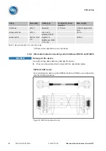
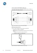
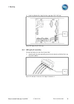
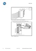
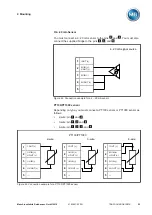
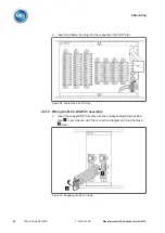
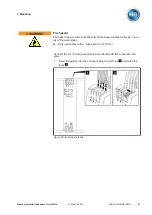
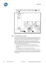
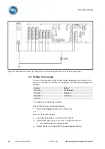
PT100/PT1000 sensor
Depending on type, you must connect a PT100 sensor or PT1000 sensor as
follows:
▪
2-wire: pin
and
▪
3-wire: pin
,
and
▪
4-wire: pin
,
,
, and
I OUT (+)
I/U IN (+)
U OUT (+)
I/U IN (-)
I/U OUT (+)
1
2
3
4
5
---
2-wire
I OUT (+)
I/U IN (+)
U OUT (+)
I/U IN (-)
I/U OUT (+)
1
2
3
4
5
---
3-wire
I OUT (+)
I/U IN (+)
U OUT (+)
I/U IN (-)
I/U OUT (+)
1
2
3
4
5
---
4-wire
PT100/PT1000
Figure 45: Connection example for a PT100/PT1000 sensor
Summary of Contents for TRAFOGUARD ISM
Page 1: ...Monitoring System TRAFOGUARD ISM Operating Instructions 5163667 00 EN ...
Page 222: ......
Page 223: ......


