10 Technical data
Maschinenfabrik Reinhausen GmbH 2016
210
5163667/00 EN
TRAFOGUARD® ISM®
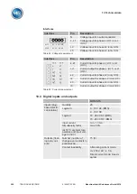
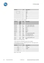
Interface
Pin
Description
1A
6A
11A
Break contact
1C
6C
11C
Source contact
1B
6B
11B
Make contact
2A
7A
12A
Break contact
2C
7C
12C
Source contact
2B
7B
12B
Make contact
3A
8A
13A
Break contact
3C
8C
13C
Source contact
3B
8B
13B
Make contact
4C
9C
14C
Source contact
4B
9B
14B
Make contact
5C
10C
15C
Source contact
5B
10B
15B
Make contact
Table 56: Digital outputs
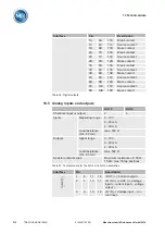
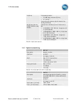
Analog inputs and outputs
AIO 2
AIO 4
Channels (input or output)
2
4
Inputs
Measuring range
0...10 V
0...20 mA
4...20 mA
Load resistance
(0/4...20 mA)
max. 300 Ω
Outputs
Signal range
0...10 V
0...20 mA
4...20 mA
Load resistance
(0/4...20 mA)
max. 500 Ω
Resistor contact series
Maximum resistance of 100 Ω...
10 kΩ, max. 35 tap positions
Table 57: Technical data for the AIO 2 and AIO 4 assemblies
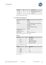
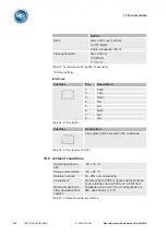
Interface
Pin
Description
1
6
11
16
I OUT (+): Current
2
7
12
17
I/U IN (+) U OUT (+): Voltage
input +, current input +, voltage
3
8
13
18
I/U IN (-): Voltage input -, cur-
rent input -
10.5
Summary of Contents for TRAFOGUARD ISM
Page 1: ...Monitoring System TRAFOGUARD ISM Operating Instructions 5163667 00 EN ...
Page 222: ......
Page 223: ......

