10 Technical data
Maschinenfabrik Reinhausen GmbH 2016
208
5163667/00 EN
TRAFOGUARD® ISM®
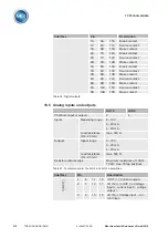
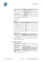
Interfaces
Interface
Pin
Description
UI 1
UI 3
N
L NC NC
N L1 L2 L3
N
Voltage input for neutral conductor
L, L1
Voltage input for phase L (UI 1) or L1
(UI 3)
L2
Voltage input for phase L2 (only UI 3)
L3
Voltage input for phase L3 (only UI 3)
Table 52: Voltage measurement
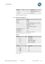
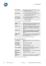
Interface
Pin
Description
k, k1
Current input for phase L (UI 1) or L1
(UI 3)
l, l1
Current output for phase L (UI 1) or L1
(UI 3)
k2
Current input for phase L2 (only UI 3)
l2
Current output for phase L2 (only UI 3)
k3
Current input for phase L3 (only UI 3)
l3
Current output for phase L3 (only UI 3)
Table 53: Current measurement
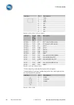
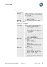
Digital inputs and outputs
DIO 28-15
Inputs (plug-
based electri-
cal isolation)
Quantity
28
Logical 0
0...10 V AC (RMS)
0...10 V DC
Logical 1
18...260 V AC (RMS)
18...260 V DC (RMS)
Input current
min. 1.3 mA
Simultaneity factor
(at 70 °C ambient tem-
perature and input volt-
age ≥ 230 V)
max. 50%
Outputs (float-
ing relay out-
puts)
Number (number of
change-over contacts in
parentheses)
15 (9)
Contact loadability
Alternating current mode:
U
N
: 230 V AC; I
N
: 5 A
Direct current mode: See di-
agram
10.4
Summary of Contents for TRAFOGUARD ISM
Page 1: ...Monitoring System TRAFOGUARD ISM Operating Instructions 5163667 00 EN ...
Page 222: ......
Page 223: ......

