3) Wenn alle Einstellungen nach folgender Be-
schreibung ausgeführt wurden, die Zeile mit der
Taste
(2) deaktivieren. Danach lässt sich ein
anderer Kamerakanal anwählen oder das Kanal-
menü ausblenden.
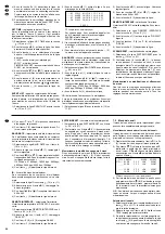
TITLE
– Kamerabezeichnung
Für die Kamerabezeichnung können bis zu sechs
Zeichen verwendet werden. Voreingestellt ist jeweils
die entsprechende Kanalnummer 01 – 16. Folgende
Zeichen stehen zur Auswahl:
0 – 9, A – Z, -, :, ), ( und _ als Leerzeichen.
1) Mit der Taste
(8) oder
(9) die Schreibstelle
anwählen, die verändert werden soll. Nach der
Aktivierung der Menüzeile ist die erste Schreib-
stelle (blinkt) angewählt.
2) Mit den Tasten
(6) und
(7) das ge-
wünschte Zeichen auswählen.
3) Den Vorgang alle weitere Zeichen wiederholen.
DWELL
– Alarmzeit für den externen Alarmeingang
Voreingestellt ist ON, wodurch bei einem Alarm über
den entsprechenden Alarmeingang der Buchse
ALARMS (22) die Alarmzeit eingehalten wird, die in
der Zeile ALARM DURATION des Hauptmenüs ein-
gestellt wurde (Voreinstellung = 2 Sekunden). Soll
der Alarm bei externer Auslösung nicht nach der ein-
gestellten Zeit beendet werden, mit der Taste
(9)
die Spalte DWELL anwählen (ON blinkt) und mit der
Taste
(6) oder
(7) auf OFF schalten.
– Einstellung von Helligkeit, Kontrast und
Farbintensität
Zur optimalen Bildeinstellung lassen sich Helligkeit
,
Kontrast und
Farbintensität verändern.
Mit
der Taste
(8) oder
(9) die entsprechende
Spalte anwählen. Der Wert lässt mit den Tasten
(6) und
(7) zwischen 0 und 9 einstellen.
ALARM
– Polarität des externen Alarmeingangs
Voreingestellt ist LOW, wodurch ein externer Alarm
durch einen Schließer (NO) oder TTL-Low-Pegel
ausgelöst wird. Zum Ändern:
1) Mit der Taste
(8) oder
(9) LOW anwählen.
LOW blinkt.
2) Mit der Taste
(6) oder
(7) HIGH einstellen,
wenn der Alarm durch einen Öffner (NC) oder
TTL-High-Pegel (5 V) ausgelöst werden soll.
3) Soll keine Auslösung über den externen Alarm-
eingang erfolgen, die Einstellung OFF wählen.
RECORD
– Aufnahmemodus
Voreingestellt ist EVENT, wodurch der Kanal bei
einem Alarm häufiger aufgezeichnet wird. Im Nor-
malaufnahmemodus ist die Bildaufzeichnungsfolge:
Kanal 1-2-3-4-...-16. Bei einem Alarm im Kanal 1
und der Einstellung EVENT ist die Bildfolge 1-2-1-3-
1-4-...-1-16, solange das Alarmsignal anliegt.
1) Mit
der
Taste (8)
oder (9)
EVENT anwählen.
EVENT blinkt.
2) Soll keine Aufzeichnung des gewählten Kanals
erfolgen, mit der Taste
(6) oder
(7) OFF
einstellen.
3) Soll bei einem Alarm der Kanal nicht häufiger auf-
gezeichnet werden, die Einstellung NORMAL
wählen.
7.3
Internen Bewegungsdetektor aktivieren
Für jeden Kamerakanal lässt sich ein interner digita-
ler Bewegungsdetektor aktiveren, der bei einer er-
kannten Bewegung im Kamerabild die Bildfolge des
Multiplexsignals zur Aufnahme erhöht, d. h. die Ka-
merakanäle werden dann häufiger aufgezeichnet.
Damit der Langzeit-Recorder in diesem Fall auch
auf Alarmaufnahme umschaltet, muss der Alarmein-
gang des Recorders an das Alarmrelais des TVMP-
2216COL angeschlossen sein und auf den Kontakt
10 „VCR trigger“ der Buchse ALARMS (22) über ei-
nen 10-k
Ω
-Widerstand eine Gleichspannung von
12 V gegeben werden, siehe auch Kap. 5.3.1.
Der Bewegungsdetektor reagiert sehr empfind-
lich auf Lichtschwankungen, wie z. B. bei sich än-
dernden Lichtreflexen, Wolken und Schatten. Diese
können einen Fehlalarm auslösen. Darum im Menü
für den Detektor möglichst ein kleines Detektions-
feld einstellen und für die Alarmauslösung eine ge-
ringe Empfindlichkeit wählen. Sollten diese Einstel-
lungen einen Fehlalarm nicht verhindern, wird
empfohlen, für den betroffenen Kanal den Detektor
nicht zu verwenden und einen externen Bewe-
gungssensor einzusetzen.
Menü für den Detektor einblenden
Dieses Menü ist ein Untermenü des Kanalmenüs.
1) Das Hauptmenü durch gleichzeitiges kurzes Drü-
cken der Tasten
(1) und
(2) einblenden.
2) Vom Hauptmenü aus mit der Taste
(7) das
Kanalmenü einblenden.
3) Mit der Taste
(10) oder
(11) die Zeile für
den gewünschten Kamerakanal anwählen. Im
Hintergrund erscheint das zugehörige Kamera-
bild.
4) Mit der Taste
(1) die Zeile für den Kamera-
kanal aktivieren. In der Spalte TITLE blinkt das
erste Zeichen.
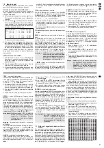
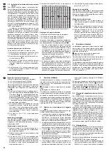
5) Die Taste MOTION (5) betätigen. Das Menü für
den internen Bewegungsdetektor erscheint:
▲
▲
Tipp
Die nicht wichtigen Kamerakanäle auf OFF
stellen. Dadurch werden die anderen Kanäle
häufiger aufgezeichnet – siehe auch ent-
sprechende Tabelle im Kapitel 9.2 „Bildrate
für die Aufzeichnung“.
▲
▲
▲
▲
▲
▲
Wichtig!
Bei der Einstellung OFF kann ein extern
ausgelöster Alarm nur durch Ausschal-
ten des Multiplexers beendet werden.
Während des Alarms sind alle Tasten
am Multiplexer gesperrt.
▲
▲
▲
▲
▲
3) If all settings were made according to the fol-
lowing description, deactivate the line with the
button
(2). Then it is possible to select another
camera channel or to extinguish the channel
menu.
TITLE
– camera designation
For the camera designation up to six characters can
be used. The corresponding channel number 01 to
16 is preset in each case. The following characters
are available for selection:
0 – 9, A – Z, -, :, ), (, and _ as a blank.
1) Select the position to be changed with the button
(8) or
(9). After activating the menu line, the
first position (flashes) is selected.
2) Select the desired character with the buttons
(6) and
(7).
3) Repeat the procedure for all further characters.
DWELL
– alarm time for the external alarm input
ON is preset, this way the alarm time adjusted in the
line ALARM DURATION of the main menu (preset-
ting = 2 seconds) is kept in case of an alarm via the
corresponding alarm input of the jack ALARMS (22).
If the alarm in case of external alarm triggering is not
to be terminated after the adjusted time, select the
column DWELL (ON flashes) with the button
(9)
and switch to OFF with the button
(6) and
(7).
– adjustment of brightness, contrast, and
colour saturation
For optimum picture adjustment, brightness
, con-
trast
, and colour saturation
can be changed.
Select the corresponding column with the button
(8) or
(9). The value can be adjusted between
0 and 9 with the buttons
(6) and
(7).
ALARM
– polarity of the external alarm input
LOW is preset by which an external alarm is trig-
gered by a closing contact (NO) or TTL low level.
To change:
1) Select LOW with the button
(8) or
(9). LOW
flashes.
2) Adjust HIGH with the button
(6) or
(7) for
triggering the alarm by an opening contact (NC)
or TTL high level (5 V).
3) If no triggering via an external alarm input is to be
made, select the setting OFF.
RECORD
– recording mode
EVENT is preset by which the channel is recorded
with increased frequency in case of alarm. In the
standard recording mode the picture recording se-
quence is as follows: channel 1-2-3-4-...-16. In case
of alarm in channel 1 and the setting EVENT the pic-
ture sequence is 1-2-1-3-1-4-...-1-16 as long as the
alarm signal is present.
1) Select EVENT with the button
(8) or
(9).
EVENT flashes.
2) If no recording of the selected channel is to be
made, adjust OFF with the button
(6) and
(7).
3) If the channel is not to be recorded with in-
creased frequency in case of alarm, select the
setting NORMAL.
7.3
Activating the internal motion detector
For each camera channel an internal digital motion
detector can be activated which increases the pic-
ture sequence of the multiplex signal for recording in
case of a recognized movement, i. e. then the cam-
era channels are recorded with increased fre-
quency. To allow the timelapse recorder to switch to
alarm recording in this case as well, the alarm input
of the recorder must be connected to the alarm relay
of the TVMP-2216COL and a direct voltage of 12 V
must be applied to the contact 10 “VCR trigger” of
the jack ALARMS (22) via a 10 k
Ω
resistor, also see
chapter 5.3.1.
The motion detector reacts very sensitively to
light fluctuations, e. g. in case of changing light re-
flections, clouds, and shadow. These may trigger a
false alarm. Therefore, adjust a small detection field
in the menu for the detector if possible and select a
minor sensitivity for the alarm triggering. If these ad-
justments should not prevent a false alarm, it is re-
commended not to use the detector for the channel
concerned and to use an external motion sensor.
Inserting the menu for the detector
This menu is a submenu of the channel menu.
1) Insert the main menu by simultaneous short
pressing of the buttons
(1) and
(2).
2) Insert the channel menu from the main menu with
the button
(7).
3) Select the line for the desired camera channel
with the button
(10) or
(11). In the back-
ground the respective camera picture is dis-
played.
4) Activate the line for the camera channel with the
button
(1). The first character flashes in the
column TITLE.
5) Actuate the button MOTION (5). The menu for
the internal motion detector is displayed:
▲
▲
Hint
Adjust the camera channels which are not im-
portant to OFF. Thus, the other channels are
recorded with increased frequency – also see
the corresponding table in chapter 9.2 “Pic-
ture rate for the recording”.
▲
▲
▲
▲
▲
▲
Important!
In case OFF is adjusted, an alarm ex-
ternally triggered can only be stopped
by switching off the multiplexer. During
the alarm all buttons at the multiplexer
are locked.
▲
▲
▲
▲
▲
13
GB
D
A
CH


