


Kanalmenü
als Untermenü des Hauptmenüs
für unterschiedliche Einstellungen der einzelnen
Kamerakanäle
Menü für den Bewegungsdetektor
als Untermenü
des Kanalmenüs zum Aktivieren und Einstellen
des Detektors für jeden Kamerakanal getrennt
7.1
Hauptmenü
Die Tasten
(1) und
(2) gleichzeitig drücken.
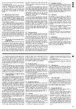
Nach dem Lösen der Tasten wird das Hauptmenü
eingeblendet:
➅
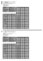
Hauptmenü mit den vom Hersteller gespeicherten Vor-
einstellungen
Jetzt können jeweils die Tasten betätigt werden, de-
ren LED leuchtet und die Beschriftung unterhalb der
Tasten ist maßgebend.
Erfolgt innerhalb einer Minute des letzten Tasten-
drucks keine weitere Eingabe, blendet sich das
Menü ohne jegliche Speicherung aus.
TITLE DISPLAY
– Kamerabezeichnung ein-/aus-
blenden
Voreingestellt ist, dass die Bezeichnungen einge-
blendet sind. Zum Ausblenden der Bezeichnungen:
1) Mit der Taste
(10) oder
(11) die Zeile TITLE
DISPLAY anwählen.
2) Mit der Taste
(1) die Zeile aktivieren. „ON“
blinkt.
3) Mit der Taste
(8) oder
(9) „OFF“ anwählen.
„OFF“ blinkt.
4) Mit der Taste
(2) die Menüzeile deaktivieren.
5) Zum Wiedereinblenden der Kamerabezeichnung
in gleicher Weise verfahren, jedoch „ON“ an-
wählen.
ALARM DURATION
– Alarmdauer
In dieser Zeile wird eingestellt, wie lange ein Alarm
andauern soll. Voreingestellt sind 2 Sekunden. Zum
Ändern der Alarmzeit:
1) Mit der Taste
(10) oder
(11) die Zeile
ALARM DURATION anwählen.
2) Mit der Taste
(1) die Zeile aktivieren. Die Se-
kundenzahl blinkt.
3) Die Alarmzeit mit den Tasten
(6) oder
(7)
zwischen 1 Sekunde und 30 Minuten einstellen.
4) Mit der Taste
(2) die Menüzeile deaktivieren.
DWELL TIME
– Verweildauer eines Bildes bei akti-
vierter Sequenzschaltung
Ist die Sequenzschaltung aktiviert (Kap. 6.3.1 bis
6.3.3), wird nach dem Ablauf der Verweildauer auf
das nächste Kamerabild gesprungen. Voreingestellt
sind 2 Sekunden. Zum Ändern dieser Zeit:
1) Mit der Taste
(10) oder
(11) die Zeile
DWELL TIME anwählen.
2) Mit der Taste
(1) die Zeile aktivieren. Die Se-
kundenzahl blinkt.
3) Die Verweildauer mit den Tasten
(6) oder
(7) zwischen 1 Sekunde und 10 Sekunden ein-
stellen.
4) Mit der Taste
(2) die Menüzeile deaktivieren.
VCR RECORD TIME
– Aufnahmemodus
Wenn am Langzeit-Recorder ein Triggerausgang
vorhanden ist und dieser mit dem Kontakt 14 „record
trigger input“ der Buchse ALARMS (22) verbunden
ist (siehe Kap. 5.3.1), synchronisiert sich der Multi-
plexer automatisch auf den Recorder. Wenn nicht,
muss in der Menüzeile VCR RECORD TIME der
gleiche Aufnahmemodus wie am Recorder einge-
stellt werden. Durch den Modus wird die Anzahl der
aufgezeichneten Bilder pro Sekunde festgelegt. Die
Einstellung erfolgt als Aufnahmedauer, die maximal
mit einer 180-Minuten-Kassette erreicht werden
kann.
1) Mit der Taste
(10) oder
(11) die Zeile VCR
RECORD TIME anwählen.
2) Mit der Taste
(1) die Zeile aktivieren. Die Stun-
denzahl blinkt.
3) Die Aufnahmedauer mit den Taste
(6) oder
(7) zwischen 3 Stunden (bei NTSC 2 Stunden)
und 960 Stunden (= 40 Tage) einstellen.
Hinweis: Je kürzer die gewählte Aufnahmedauer
ist, desto öfter wird ein Bild an den Recorder ge-
geben und desto lückenloser lässt sich später die
Wiedergabe betrachten. Weitere Informationen
siehe Kapitel 9.2 „Bildrate für die Aufzeichnung“.
4) Mit der Taste
(2) die Menüzeile deaktivieren.
ALARM VCR RECORD TIME
– Alarm-Aufnahme-
modus
Um bei einem Alarm eine häufigere Bildfolge für die
Aufzeichnung als unter VCR RECORD TIME einge-
stellt zu erhalten, kann der Recorder vom Alarm-Re-
lais des Multiplexers von Langzeitaufnahme auf
Alarmaufnahme geschaltet werden (Kapitel 5.3.1).
Dazu muss der Multiplexer über den Kontakt 14 der
Buchse ALARMS (22) vom Recorder synchronisiert
oder im Menü die gleiche Alarm-Aufnahmedauer
wie am Recorder eingestellt werden:
1) Mit der Taste
(10) oder
(11) die Zeile
ALARM VCR RECORD TIME anwählen.
2) Mit der Taste
(1) die Zeile aktivieren. Die Stun-
denzahl blinkt.
▲
▲
▲
▲
▲
▲
▲
▲
▲
▲
➧
TITLE DISPLAY:
ON
OFF
ALARM DURATION: 02 SECOND
DWELL TIME: 02 SEC
VCR RECORD TIME: 003 HOUR
ALARM VCR RECORD TIME: 003 HOUR
INT AUDIBLE ALARM:
ON
OFF
EXT AUDIBLE ALARM:
ON
OFF
EVENT MESSAGE LATCH: ON
OFF
SECURITY LOCK: ON
OFF
SET TIME: 00/01/01 00:00:00 Y/M/D
EVENT LIST
BAUD RATE: 9600 BPS
ID: 000
REMOTE INTERFACE: RS-485
RS-232C
SYSTEM RESET
▲
7.1
Main menu
Press the buttons
(1) and
(2) at the same time.
After releasing the buttons, the main menu is in-
serted:
➅
The main menu with the presettings memorized by the
manufacturer
Now the buttons can be actuated of which the LED
lights up. The lettering below the buttons is decisive.
If no further entry is made within one minute after the
last pressing of the button, the menu extinguishes
without any storage.
TITLE DISPLAY
– insert/extinguish the camera
designation
It is preset that the designations are inserted. To ex-
tinguish the designations:
1) Select the line TITLE DISPLAY with the button
(10) or
(11).
2) Activate the line with the button
(1).
“ON” flashes.
3) Select “OFF” with the button
(8) or
(9).
“OFF” flashes.
4) Deactivate the menu line with the button
(2).
5) To insert the camera designation again, proceed
the same way but select “ON”.
ALARM DURATION
The alarm time is set in this line. 2 seconds are pre-
set. To change the alarm time:
1) Select the line ALARM DURATION with the but-
ton (10)
or (11).
2) Activate the line with the button
(1). The num-
ber of seconds flashes.
3) Set the alarm time between 1 second and 30 min-
utes with the buttons
(6) or
(7).
4) Deactivate the menu line with the button
(2).
DWELL TIME
of a picture with activated sequential
switching
If the sequential switching is activated (chapter 6.3.1
to 6.3.3), the unit goes to the next camera picture
after the dwell time has elapsed. 2 seconds are pre-
set. To change this time:
1) Select the line DWELL TIME with the button
(10) or
(11).
2) Activate the line with the button
(1). The num-
ber of seconds flashes.
3) Set the dwell time between 1 second and 10 sec-
onds with the buttons
(6) or
(7).
4) Deactivate the menu line with the button
(2).
VCR RECORD TIME
– recording mode
If a trigger output is provided at the timelapse re-
corder and this output is connected to the contact 14
“record trigger input” of the jack ALARMS (22) [see
chapter 5.3.1], the multiplexer is automatically syn-
chronized to the recorder. If not, the same recording
mode as on the recorder has to be adjusted in the
menu line VCR RECORD TIME. The mode defines
the number of the recorded pictures per second.
The adjustment is made as recording time which
can be reached with a 180-minute tape cassette as
a maximum.
1) Select the line VCR RECORD TIME with the but-
ton (10)
or (11).
2) Activate the line with the button
(1). The num-
ber of hours flashes.
3) Adjust the recording time between 3 hours (in
case of NTSC 2 hours) and 960 hours (= 40
days) with the button
(6) or
(7).
Note: The shorter the selected recording time,
the more frequently a picture is sent to the re-
corder and the less interruptions will occur if the
reproduction is regarded later. Further informa-
tion see chapter 9.2 “Picture rate for the re-
cording”.
4) Deactivate the menu line with the button
(2).
ALARM VCR RECORD TIME
– alarm recording
mode
To obtain a picture sequence of increased frequency
for the recording in case of alarm compared to that
adjusted under VCR RECORD TIME, the recorder
can be switched by the alarm relay of the multiplexer
from timelapse recording to alarm recording (chap-
ter 5.3.1). For this purpose the multiplexer has to be
synchronized via the contact 14 of the jack ALARMS
(22) by the recorder or the same alarm recording
time as on the recorder has to be adjusted in the
menu:
1) Select the line ALARM VCR RECORD TIME with
the
button (10)
or (11).
2) Activate the line with the button
(1). The num-
ber of hours flashes.
3) Adjust the alarm recording time with the buttons
(6) and
(7) between 3 hours (in case of
NTSC 2 hours) and 960 hours (= 40 days). How-
ever, it should be shorter than the time adjusted
in the line VCR RECORD TIME, otherwise this
function is pointless.
4) Deactivate the menu line with the button
(2).
▲
▲
▲
▲
▲
▲
▲
▲
▲
▲
▲
▲
▲
➧
TITLE DISPLAY:
ON
OFF
ALARM DURATION: 02 SECOND
DWELL TIME: 02 SEC
VCR RECORD TIME: 003 HOUR
ALARM VCR RECORD TIME: 003 HOUR
INT AUDIBLE ALARM:
ON
OFF
EXT AUDIBLE ALARM:
ON
OFF
EVENT MESSAGE LATCH: ON
OFF
SECURITY LOCK: ON
OFF
SET TIME: 00/01/01 00:00:00 Y/M/D
EVENT LIST
BAUD RATE: 9600 BPS
ID: 000
REMOTE INTERFACE: RS-485
RS-232C
SYSTEM RESET
▲
10
GB
D
A
CH