1
ET3260
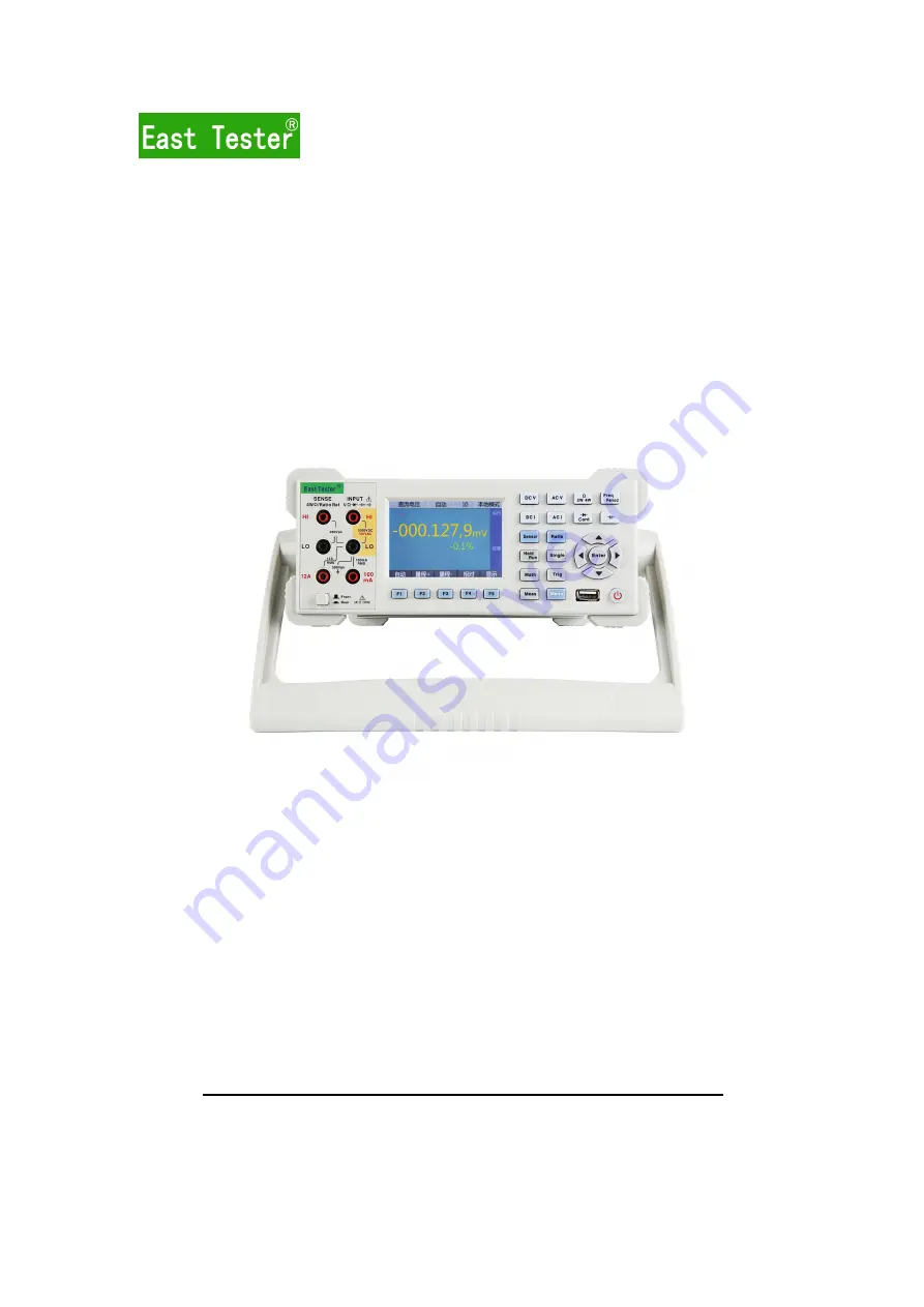
6 1/2 Digit Multimeter
ET3260A 6 1/2 Digit Multimeter
User Manual
Hangzhou Zhongchuang Electron Co., Ltd.
Page 1: ...1 ET3260 6 1 2 Digit Multimeter ET3260A 6 1 2 Digit Multimeter User Manual Hangzhou Zhongchuang Electron Co Ltd...
Page 2: ...tly use leading wire suite Please do not use damaged or worn out leading wire suite which may cause instrument damage or personal injury During probe using the fingers should be kept behind finger pro...
Page 3: ...t of measurement range from 10uA to 100mA and current input fuses on the rear panel provide 500mA protection limit at most to the current through 500mA terminal Note In order to avoid fuse blowout and...
Page 4: ...measure circuits where transient overvoltages could exceed this level Environmental Precautions The product complies with requirements indicated in WEEE Directive 2002 96 EC The affixed product label...
Page 5: ...two parameters in one input signal such as display AC voltage value and AC frequency value during AC voltage measurement Conduct remote operation through interfaces of IEEE 488 ET3260 RS 232 LAN and U...
Page 6: ...nce measurement 22 2 1 9 Continuity measurement 23 2 1 10 Diode measurement 23 2 2 Usage of Sensor 24 2 2 1 Thermal resistance sensor 24 3 Characteristic and Function 24 3 1 Measurement Configuration...
Page 7: ...tive force error 39 5 1 2 DCV load error 39 5 1 3 DCI load error 40 5 1 4 Noise control 40 5 1 5 Resistance measurement considerations 42 5 2 AC Measurement Considerations 42 5 2 1 True virtual value...
Page 8: ...This 6 1 2 digit multimeter provides a 480 320 TFT display and the equipped display can indicate current working status F1 F5 software define area measured value etc No Introduction 1 HI and LO sense...
Page 9: ...esistance 4 wire frequency period on off diode sensor capacitance and ratio among which resistance 2 wire and resistance 4 wire share one key frequency and period share one and on off and diode share...
Page 10: ...et display system information etc Redefine function 1 3 Rear Panel No Introduction 1 Power outlet 2 Power fuses 3 Power switch 4 Voltage selector 5 VCM output voltmeter completes measurement output 6...
Page 11: ...power voltage selector installed on multimeter rear panel according to your power supply voltage 2 Connect the multimeter to AC power with power line supplied by accessories 2 Start multimeter Turn o...
Page 12: ...during AC voltage measurement with major display being voltage measurement value and auxiliary display frequency measurement value Statistic data display interface Statistic Data Display Description U...
Page 13: ...er of measurement points the first record value is 0 and increases by 1 every time gain a new measurement value ordinate axis represents measurement value 1 7 Measurement Wiring Note The main input LO...
Page 14: ...0mA input terminals are not allowed to be connected to the current measurement loops at the same time Press to select DC current measurement function 1A 12A measurement is as shown in the following fi...
Page 15: ...uct Basic Measurement 2 1 1 DC voltage measurement Basic information Measurement range 100mV 1V 10V 100V and 1000V Maximum resolution 100nV Operation description Press to select frequency measurement...
Page 16: ...switch modes and refer to the chapter of User interface for details 6 If necessary press to configure the following measurement parameters integral time input impedance and zero calibration method and...
Page 17: ...chapter of Measurement configuration for details 2 1 3 AC voltage measurement Basic information Measurement range 100mV 1V 10V 100V and 750V AC technology true virtual value measurement and AC coupli...
Page 18: ...and high current measurement with different wiring methods Low current measurement range 10uA 100uA 1mA 10mA and 100mA High current measurement range 1A and 12A Maximum resolution 10pA Operation descr...
Page 19: ...isplayed value refers to measurement current value and auxiliary displayed value refers to frequency measurement value of the current input signal 2 Connect test lines as indicated in the chapter of 1...
Page 20: ...ement wiring 3 Select measurement range as required and may select automatic measurement or press the softkeys of Measurement range and Measurement range to select fixed measurement range which have s...
Page 21: ...information Frequency measurement band 3Hz to 300 kHz Period measurement band 3 3us to 0 33s Measurement range 100mV 1V 10V 100V and 750V Input signal range 100mVAC to 750VAC Technology equal precisi...
Page 22: ...to measurement capacitance value and auxiliary displayed value refers to the ratio between the measurement value and full measurement range 3 Connect test lines as indicated in the chapter of 1 4 Mea...
Page 23: ...the beeper threshold display resistance value 2 Connect test lines as indicated in the chapter of 1 4 Measurement wiring 3 Press the softkey of Setup to set beeper threshold when the measured resista...
Page 24: ...as is required press the softkeys of Graduation mark and Graduation mark or keys of and 4 Press the softkey of Relative to record the current value after which display the difference between actual me...
Page 25: ...t a continuous individual tone Threshold resistance value can be set as any number from 1 to 1000 which can only be adjusted on the front panel Threshold resistance is stored in volatile memory and af...
Page 26: ...power period is as follows Resolution Integral Time High speed 4 1 2 0 02 PLC Low speed 4 1 2 0 1PLC High speed 5 1 2 0 2PLC Low speed 5 1 2 1PLC High speed 6 1 2 2PLC Mid speed 6 1 2 10PLC Low speed...
Page 27: ...integral times through keys of and and then press 3 1 6 Switch between front rear input terminals All the measurement conducted by input terminal can also be conducted by input terminal on rear termin...
Page 28: ...ver measurement range appearing on front panel During frequency and period measurement multimeter only uses one measurement range to include all the input signals from 3Hz to 300 kHz During continuity...
Page 29: ...e between input signal and existing relative value the two are both converted to dBm dB reading in dBm relative value in dBm The following table shows possible combination between math operation funct...
Page 30: ...elative value to 0 Press softkeys of On Off to start or stop relative operation and after starting Relative indication can be seen on the right side of main interface After setting press the softkey o...
Page 31: ...key of Default to reset the Relative value to 0 After setting press the softkey of Exit to go back to the former layer interface 3 2 4 Limit test Limit test function can be used to test whether it exc...
Page 32: ...or lower limit with Excessively higher meaning exceed the specified upper limit and Excessively lower meaning exceed the specified lower limit When status switches from Pass to Excessively higher or...
Page 33: ...eading on screen Single trigger When the trigger source is set as auto trigger the Single indicator in status column will light on and multimeter will capture one reading or readings in specified numb...
Page 34: ...ives trigger signal it will read readings in specified number The selected samples are stored in volatile memory and multimeter will set the samples as 1 after cutting off power or resetting remote in...
Page 35: ...ve the record into USB drive When the USB interface on front panel is connected to USB drive it can save history data to the measRecords folder under USB drive s root directory with the measurement da...
Page 36: ...start or stop beeper output Press the softkey of Recover to restore to factory setting 3 5 2 Command set ET3260 and 3260A are compatible with command sets of Agilent 34401A Agilent 34410A and Fluke45...
Page 37: ...y copy the software update package to this folder and plug the USB driver into the USB interface on multimeter front panel Press the key of System update after all the preparations to update the syste...
Page 38: ...parameters to set multimeter and connect multimeter to computer USB terminal Pay attention to that computer might need several seconds to identify and establish connection with multimeter 4 4 LAN Inte...
Page 39: ...ltage measurement And the best connecting method is copper copper crimping for the multimeter input terminal is made from red copper The following table lists common thermal voltage during heterogeneo...
Page 40: ...ou should select multimeter s next higher measurement range to reduce the error to an acceptable level The following table lists multimeter internal resistances under different measurement ranges Meas...
Page 41: ...uch as possible Test lead looseness or vibration may cause induction error voltage Fasten test leads when operating near magnetic field and if possible try to use magnetic shielding material or keep a...
Page 42: ...lead and contact resistance and is generally used for automation test under the situation where there are resistance long cable or plentiful connections or switches between multimeter and equipment u...
Page 43: ...low AC signal of high DC offset during measurement AC coupling true virtual value measurement is quite useful For example it is a common situation of measuring AC ripple wave existing in DC power How...
Page 44: ...g 0 03 of the measurement range 5 2 3 ACV load error When using AC voltage measurement function multimeter input impedance is 1M with resistance being connected to 100pF capacitance in paralleled way...
Page 45: ...r pre heating and in using Auto Zero function and the 24 hour indicator is relative to calibration standard and test standard complies with GB T 13978 2008 Digit Multimeter 6 1 DC Characteristics 6 1...
Page 46: ...ranges other measurement ranges are all 1k wire Current source accuracy 3 On off test On off threshold 1 1000 which can be set by users Test current 1mA 3 Response time 300 samples second Display res...
Page 47: ...0 200 1500 200 50 20 Resistance 4 10 10u 10mA 30 30 80 40 100 40 6 5 100 100u 1mA 30 30 80 40 100 40 6 5 1k 1m 1mA 20 5 70 10 100 10 6 1 10k 10m 100uA 20 5 70 10 100 10 6 1 100k 100m 50uA 20 5 70 10 1...
Page 48: ...or is 0 13 of the measurement range Maximum input 750Vrms Input impedance 1 M 1 shunt capacitance 100pF Measurement method AC coupling virtual value response Maximum DC offset not lower than 1000V AC...
Page 49: ...0 12 0 05 0 011 0 005 50k 100kHz 4 0 55 0 08 0 60 0 08 0 60 0 08 0 060 0 008 100k 300kHz 3 4 00 0 50 4 00 0 50 4 00 0 50 0 20 0 02 AC current 100uA 100 pA 3Hz 5 Hz 1 0 0 04 1 0 0 04 1 0 0 04 0 100 0 0...
Page 50: ...eristics Gate time can be set as 1s 100ms and 10ms or a wider range Stability refers that after DC offset voltage changes the time to reach stable and accurate measurement result is not longer than 1...
Page 51: ...nF 10uA 10pF 2sps 1 0 3 0 05 0 01 100nF 100uA 100pF 2sps 1 0 3 0 01 0 01 1uF 1mA 1nF 2sps 1 0 3 0 01 0 01 10uF 1mA 10nF 2sps 1 0 3 0 01 0 01 100uF 1mA 0 1uF 2sps 1 0 3 0 01 0 01 1000uF 10mA 1uF 2sps 1...