


6
- 8
6.2 Fail-Safe Circuit
6
PREPARATORY PROCEDURES AND SETTING
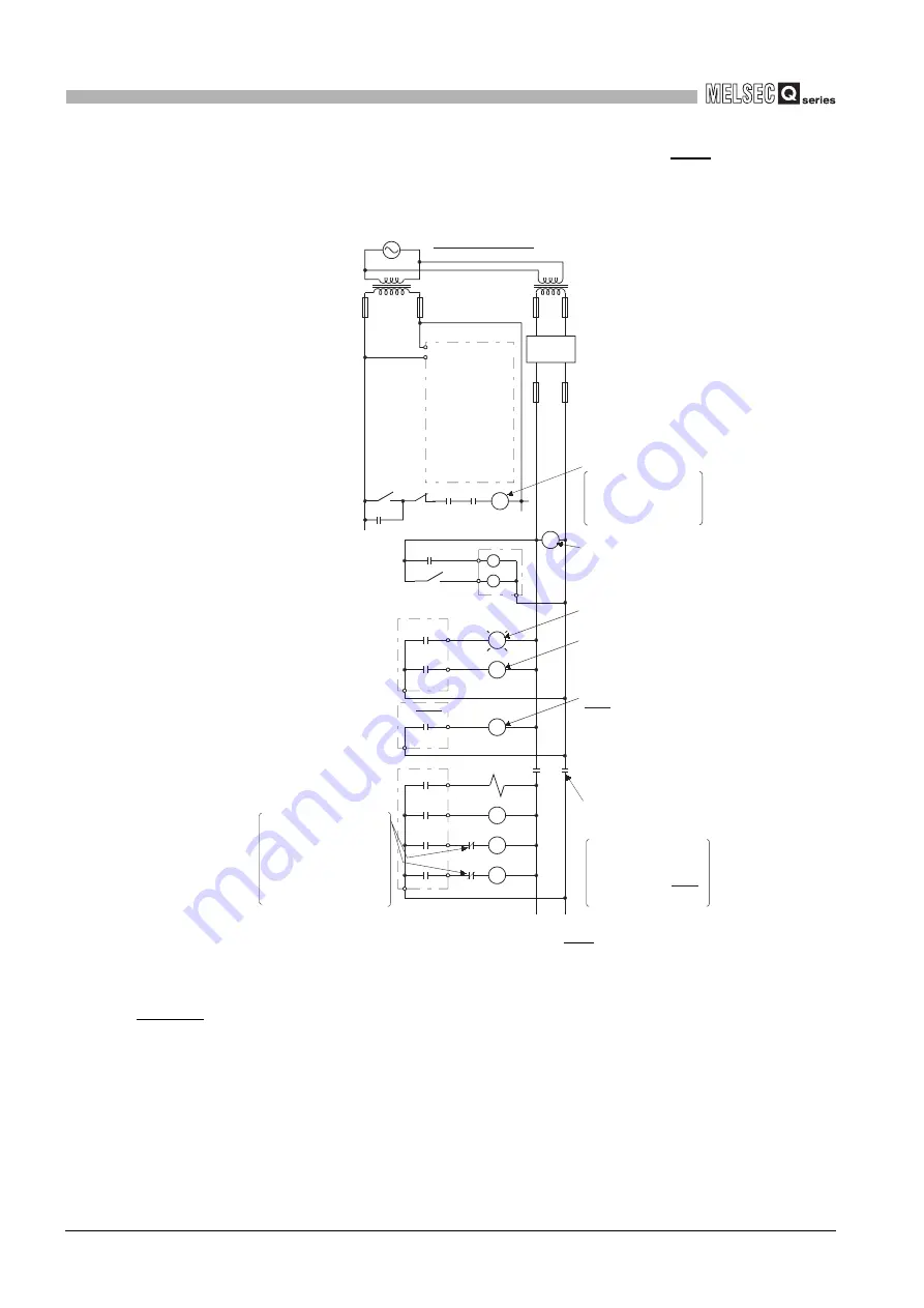
(2) Circuit example for system design (When using the ERR. contact of the
power supply module)
Figure 6.4 Circuit example for system design (when using the ERR. contact of the power supply module)
The power-up procedure is as follows:
For AC/DC
[1] Turn on the power.
[2] Set the C Controller module to "RUN".
[3] When DC power is applied, RA2 is turned on.
[4] When RA2 turns on, XM is turned on.
Upon 100% establishment of the DC input signal, processing is started by the user program.
*1
[5] Turn on the start switch.
[6] When the magnetic contactor (MC) turns on, the output equipment is driven by the user program.
This relay turns off if the
ERR. contact turns off
(a stop error occurs).
MC
RA1 RA3
RA2
XM
Ym
Yn
MC2
MC1
MC MC
MC
RA2
L
MC1
RA1
MC2
(-)(+)
FOR AC/DC
Power supply
Started when RA1
(control start output of
C Controller module)
turns ON.
RUN/STOP circuit
Interlock circuits
Transformer Transformer
Fuse
Fuse
Fuse
DC
power
Voltage relay is
recommended
Low battery alarm
(Lamp or buzzer)
Turns ON at start of
C Controller module
user program.
The stop switch turns
off by an emergency
stop, a stop caused by
exceeding a limit value,
or turning off the ERR.
contact.
START
SW
STOP
SW
Output module
ERR.
RA3
Power supply module
Output module
Provide external
interlock circuits for
conflicting operations,
such as forward rotation
and reverse rotation,
and for parts that could
damage the machine or
cause accidents .
Power to output
equipment is turned
off when the STOP
signal is given.
User
program
*1
C Controller module
Summary of Contents for Q06CCPU-V
Page 2: ......
Page 612: ...APPX 48 Appendix 11 Functions Added by Version Upgrade APPENDICES Memo ...
Page 617: ......


