background image

Chapter 3 Setup

3-2

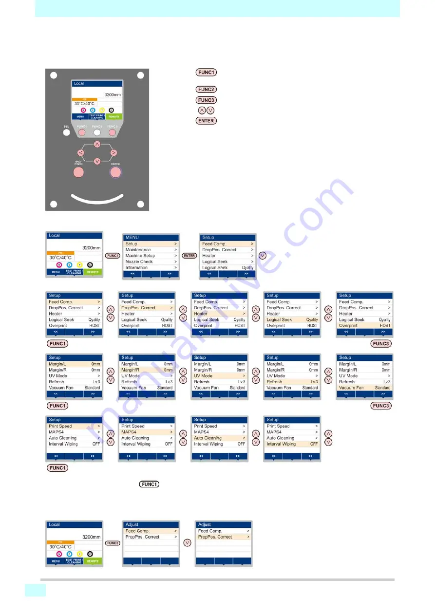
About Setup MENU

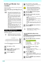
On Setup MENU, you can set the print conditions to match the media you usually use.

Screen transition when 

 (ADJUST)  key is pressed

When  adjustment  functions  (Feed  Comp./  X-Distance  Comp./  Prop  Pos.  Correct)  are  performed,  the  ADJUST
MENU can be displayed easily without selecting [MENU]-[Setup] from Local. 
Press the [SEL] key to display “ADJUST” for [FUNC1], and then press the [FUNC1] key.

: Press  this  to  select  SETTING  MENU,  or  to  switch  to  the

previous screen.

: Press this to use the adjust function.
: Press this to switch to the next screen.
: Use these to select a setting item.
: Press this to confirm a setting, etc..

SETUP MENUs at-a-glance

Summary of Contents for SIJ-320UV

Page 1: ...MIMAKI ENGINEERING CO LTD URL http mimaki com D202809 13 Original instructions ...

Page 2: ...1 7 Media sensor 1 7 Carriage 1 7 Capping station 1 8 Pinch rollers and Feed rollers 1 8 Connecting Cables 1 8 Connecting USB2 0 Interface Cable 1 8 Connecting Power Supply Cable 1 9 Fill ink in the ink tank and charging 1 10 Caution in handling of ink bottles 1 12 Media 1 13 Usable sizes of media 1 13 Caution in handling of medias 1 13 Chapter 2 Basic Operations Workflow 2 2 Turning the Power ON ...

Page 3: ...g of Logical Seek 3 6 Setting of Overprint 3 6 Setting of Left and Right Margins 3 7 Setting of UV mode 3 7 Setting of Refresh 3 9 Setting of Vacuum Fan 3 9 Setting of Print Speed 3 9 Setting of MAPS4 3 10 Setting Auto Cleaning 3 10 Setting Interval wiping 3 11 About Machine Setup MENU 3 12 Machine Setup MENU table 3 13 Setting a AUTO Power off 3 13 Setting Feeding unit 3 13 Setting Take up unit 3...

Page 4: ...aning the Ink Head and the Area around It 4 12 When nozzle missing Cannot Be Solved 4 13 Washing the Head Nozzle 4 13 Nozzle Recovery Function 4 14 Automatic Maintenance Function 4 16 Setting the Refreshing level 4 16 Setting the Cleaning level 4 16 Discarding waste ink 4 17 For waste ink remaining management 4 18 Adjust the waste ink 4 19 Replacing consumables 4 20 Replacing the wiper 4 20 Replac...

Page 5: ...When media heaves up at feeding 5 6 Warning Error Messages 5 7 Warning messages 5 7 Error messages 5 12 Chapter 6 Appendix Specifications 6 2 Machine specifications 6 2 Ink specifications 6 3 Supply item list 6 3 Setting orders of ink tanks 6 4 Sheet for inquiry 6 5 ...

Page 6: ...nt that the product is the cause of interference try to eliminate it by taking one of the following corrective measures or taking some of them in combination Change the orientation of the antenna of the television set or radio to find a position without reception difficulty Separate the television set or radio from this product Plug the power cord of this product into an outlet which is isolated f...

Page 7: ...e in a damp environment Do not splash water onto the machine Use in such an environment can give rise to fire electric shocks or breakdown of the machine Use it with the displayed power supply specifications The power supply voltage of this machine shall be single phase 200 to 240 Vac 15A and less You cannot use this machine in the 100V system Use of the machine under an abnormal condition where i...

Page 8: ...to cause fire or electric shocks Connect to a socket outlet with determinate polarity Power supply Leave the breaker turned ON Do not turn off the main power switch on the right side of this machine Heater Do not spill liquid on the pre heater as this may cause failure of the heater or firing Do not touch pre heater heaters with bare hand while it is hot otherwise you can get burned Note on mainte...

Page 9: ... units used Never use those UV devices other than those recommended by Mimaki We would take no responsibility for any troubles caused through the use of a UV devices not recommended by Mimaki CAUTION Lay a mat or fabric on the floor About cleaning After using the unit long time foreign materials and dust may be gathered on the conductive and insulating parts causing electric leakage Periodically c...

Page 10: ...s of the media used Automatic temperature setting can be made on the operation panel by setting the profile on the dedicated RIP For setting on the RIP refer to the instruction manual for your RIP Pay attention to the expansion and contraction of the media Do not use media immediately after unpacking The media can be affected by the room temperature and humidity and thus it may expand and contract...

Page 11: ...ined surface A place that vibrates A place exposed to direct air flow from an air conditioner or the like A place where temperature or humidity varies significantly Around a place where fire is used Use the machine under the following environmental conditions Operating environment 20 to 30 C 68 to 86 F 35 to 65 Rh ...

Page 12: ...rning labels are stuck on the machine Be sure to fully understand the warning given on the labels If a warning label is illegible due to stains or has come off purchase a new one from a distributor or our sales office Around the caridge ...

Page 13: ...xii Warning labels 1 2 2 2 2 2 1 No Reorder Label 1 M905811 2 M903330 3 M905980 4 M907935 5 M903239 6 M903404 ...

Page 14: ...xiii Warning labels ...

Page 15: ... Names of Parts and Functions 1 3 Front Side of the Machine 1 3 Rear Side and Right Side of the Machine 1 4 Operation Panel 1 5 Pre Heater 1 7 Media sensor 1 7 Carriage 1 7 Capping station 1 8 Pinch rollers and Feed rollers 1 8 Connecting Cables 1 8 Connecting USB2 0 Interface Cable 1 8 Connecting Power Supply Cable 1 9 Fill ink in the ink tank and charging 1 10 Caution in handling of ink bottles ...

Page 16: ...ng machine The leg of this machine has the level foot to fix the machine Before turning the power ON make sure that the printer body is fixed with the leveling feet The printer body may start moving during operation if it is not fixed with the leveling feet Moving This Machine Model Width Depth Height Gross weight SIJ 320UV 5410mm 995mm 1440mm 850 kg If the place to install the machine is exposed ...

Page 17: ...up and down to hold or release the media Tension bar Brings tension to the media Stand Supports the main body of the machine Left side maintenance cover Open the cover in maintenance Even when the power button is off keep all covers closed Platen The printed media is sent out sliding on the platen Rght side maintenance cover Open the cover in maintenance inside the station Take up unit Take up the...

Page 18: ...ctor Roll holders Uses when printing a media of vinyl chloride or photo paper Pre heater Preheats the media before printing Located inside the cover Rear cover Open the cover in setting of medias taking of measures against jamming of medias Even when the power button is off keep this cover and the other covers closed Tension bar Brings tension to the media Ink supply unit Set the ink tank Wide med...

Page 19: ...YSTEM HALT has occurred Display Displays the following items Printer status Set media width Heater temperature current tem perature set temperature Ink status 1 Functions assigned to FUNC1 to FUNC3 2 key Changes over the functions of the function keys FUNC1 FUNC3 key Press this to set various functions or to do test printing The function keys functions are changed each time SEL key is pressed JOG ...

Page 20: ...es to the next page When there are multiple items on the MENU screen or other screens it moves to the previous page Used for completing confirmation when warning message has been displayed and so on Used for turning functions OFF or cancelling them for example when turning heater settings OFF and so on Some kind of setting or function is assigned Operate according to the description of each functi...

Page 21: ... is made while the pre heater cover is hot the thin media might stick fast to the platen or get wrinkled or curled If the media floats as wave press the button on the operation panel to feed the media Pre heater cover Pre heater When setting a media be sure to cover one of the media sensors located on the rear of the pre heater cover The media cannot be detected unless it is placed over the sensor...

Page 22: ...rmally Reconnect the unrecognized SIJ 320UV machine to another USB port if available and check to see if it is recognized If the SIJ 320UV machine is not recognized by the newly connected USB port use USB 2 0 repeater cables available on the market Be sure to wear the attached goggles in cleaning within the capping station to protect your eyes against ink Otherwise you may get ink in your eyes If ...

Page 23: ...er uses the Type B plug and socket in compliance with IEC 60309 When a socket construction meeting the plug of the power cable of this printer is required use the supplied socket and perform construction between your switchboard and the socket The power supply specifications of this machine is as below Single phase 200 to 240 Vac 15A cannot be used with 100 V system For the power supply to the mai...

Page 24: ...h expiration dates of the ink contained in the ink bottle for refilling and the ink tank of this machine Check the label for the expiration date of the ink bottle Press the ENTER key to check the expiration date of the ink remaining in the ink tank of this machine P 3 22 Ink remaining amount indicator Line of mouth for Status of ink remainingamount indicator Status of ink amount Ink near end Ink e...

Page 25: ...chip Do not reuse IC chips If the error message INVALID INK CHARGE appears on the display Charging was not possible for one or more of the following reasons 1 Faulty IC chip 2 The remaining amount of ink managed by this machine is FULL 3 Attempting to charge ink that has passed its expiration date Before shaking it check that the cap is firmly closed If you shake it too strong it may cause ink lea...

Page 26: ...tember 2015 October Usable November Usable December Unusable Caution in handling of ink bottles When the ink is unusable printing and or cleaning operation and charging with the IC chip P 1 10 are disabled In such a case discard the ink remaining in the ink tank of this machine and refill new ink P 1 10 Ink color Indication mark Black one black circle Cyan one blue circle Magenta one red circle Ye...

Page 27: ...due to fingerprints or oil of your finger Be careful about it Do not leave the media with the heater ON for a long time Waviness may occur on the media and it may cause media clogging Use media recommended by MIMAKI to ensure reliable high quality printing Set the heater temperature to meet the characteristics of the media Set the temperature of the Pre heater according to the type and characteris...

Page 28: ...1 14 Chapter 1 Before Use ...

Page 29: ...a 2 16 Removing the taken up media 2 16 Changing the printing origin 2 17 Preparing for the Heaters 2 18 Changing the Temperature Settings for the Heaters 2 18 Test Printing 2 18 Test Printing 2 19 Head Cleaning 2 19 About head cleaning 2 19 Perform head cleaning depending on the test printing result 2 19 Setting of Media Correction 2 20 Setting of Media Correction 2 20 Correct the ink drop positi...

Page 30: ... 4 Test Printing Referring to Test Printing P 2 18 Head Cleaning Referring to Head Cleaning P 2 19 Correct the media feed amount Referring to Setting of Media Correction P 2 20 Correct the ink drop position for bidirectional printing Referring to Correct the ink drop position for bidirectional printing P 2 21 Printing Data Referring to Printing Data P 2 22 ...

Page 31: ...ain press the END POWER key Cautions about Turning the Power OFF Do not turn the main power switch OFF When the main power switch is ON the power periodically turns ON and the nozzle missing prevention function flushing function operate When the main power switch has been turned OFF the auto maintenance functions such as flushing do not operate and this may cause nozzle missing Keep the front cove...

Page 32: ...en stained with ink traces In the following cases perform P 2 21 Correct the ink drop position for bidirectional printing The lever position is changed The head height is not changed but the media thickness is changed Take care not to drop the media on your foot when setting the media It may cause an injury due to the media When setting a roll media work by two or more people Otherwise you may hur...

Page 33: ...formed properly For setting a narrow roll media refer to Setting a narrow roll media P 2 9 When using a take up device it is recommended to set the media with its print side facing inside This machine allows a media to be set with its print side facing either inside or outside Setting the print side facing inside reduces the variations in tension caused by the changes in the media diameter occurri...

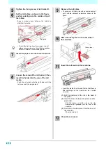
Page 34: ...ack to the front Make the Feeding manual switch AUTO 10 Close the rear cover Backward Feeding with the print side facing to the inside OFF Not operated Manual Auto Feeding direction switch Forward Feeding with the print side facing to the outside Feeding manual switch Tension bar Lock Tension bar Insert the roll media between the platen and the pinch roller and slide it to the front Pull the media...

Page 35: ...the roll shaft 1 Route the media from the front side of the tension bar and fix the media in the center of the roll shaft with adhesive tape 2 In the same manner fix the left side and right side of the media Pull roll media evenly for right and left check that there is no slack or waviness on the media and paste tape in numerical order When you place the tape consider the rolling up direction You ...

Page 36: ...ity 2 Press the ENTER key When Media Remain of the machine setup is ON P 3 14 you are prompted to enter the media remaining amount P 2 9 To take up the media with its print side facing inside Set the taking up direction switch to Backward To take up the media with its print side facing outside Set the taking up direction switch to Forward To stop taking up Set the taking up direction switch to neu...

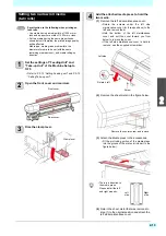
Page 37: ...he screen of Setting a roll media as described in step 21 is displayed Follow the steps 22 and later Setting a narrow roll media When you use narrow roll media up to 1 6m set the media on the narrow roll holder 1 Set the setting of the feeding unit to OFF in Setting Feeding unit of the machine setting P 3 13 2 Open the front cover and rear cover 3 Move the media press to outside 4 Move the roll ho...

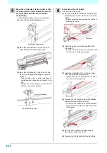
Page 38: ...y upward as shown in the figure 10 Raise the clamp lever in the rear side of this machine 11 Insert the roll media in this machine Insert the media from the end first so that there is little catching and the media can be inserted smoothly 1 Pull the media out of the roll to the head of the platen 2 Insert the media between the platen and the pinch roller Pull the media out of the roll so that the ...

Page 39: ... bar on the front side to the highest position and lock the bar 18 Feed the media to the tension bar 1 Pressing the key feed the media until the tension bar at the rolling side is being hidden Check the media end is not caught into the slot on the platen and feed the media 19 Fix the media to the roll shaft 1 Route the media from the front side of the tension bar and fix the media in the center of...

Page 40: ...y When Media Remain of the Machine Setup is ON P 3 14 you are prompted to enter the media remaining amount P 2 9 To take up the media with its print side facing inside Set the taking up direction switch to Backward To take up the media with its print side facing outside Set the taking up direction switch to Forward To stop taking up Set the taking up direction switch to neutral OFF Tension bar Loc...

Page 41: ...figure below 3 Attach the Media press in the accessories Fit the protruding portion of the media press into the groove of the platen circle part in the figure below 4 Return the sheet metal that was removed in step 1 to the original position and attach the left side maintenance cover Pay attention to the following when printing on twin rolls Use media having a media width of 1524 mm or less and a ...

Page 42: ... Set the roll tables as shown in the figure and temporarily place the media on top of the tables Keep a proper space between the tables to stabilize the media 2 Insert the paper core of the media into the roll holder C Push the roll media onto the roll holder until the roll core is all the way seated 3 Insert the roll holder R or L into the paper core and tighten the fixing screw Tighten the screw...

Page 43: ...e media press from the media before printing 12 Close the front cover 13 Press the key to select ROLL If the Setting the Display of Media Detection of Machine Setup set in AUTO P 3 15 the machine automatically detects the media width 14 Setting the Logical Seek 1 Press to select the set value Set value Media Data Quality 2 Press the ENTER key When Media Remain of the Machine Setup is ON P 3 14 you...

Page 44: ...the media straight 5 Press the key 6 Press the key to select LEAF If the Setting the Display of Media Detection of Machine Setup set in AUTO P 3 15 the machine automatically detects the media width 7 Setting the Logical Seek 1 Press to select the set value Set value Media Data Quality 2 Press the ENTER key P 2 9When Media Remain of the Machine Setup is ON P 3 14 you are prompted to enter the media...

Page 45: ... and media moving the point with Position of the LED pointer becomes the origin position 3 After determining the origin press the key The printing origin is changed When a roll media is set on the narrow roll holder change the origin and then rewind the media by hand and set the media without slack If the media is loose the media feed amount of the media varies causing poor image quality Origin Le...

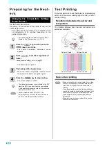
Page 46: ...ip between head row and test pattern The relations between head row and test pattern print position are as follow Note on test printing You can change the temperature set here also in Heater of the Setup menu P 3 5 The Heater temperature is controllable at the RIP side if the RIP in use has a function controllable For the setting procedures refer to the instruction manual of the RIP in use Use thi...

Page 47: ...proved even by Normal or Soft cleaning Perform head cleaning depending on the test printing result There are three types of head cleaning Use one by checking the test pattern 1 Press the TEST PRINT CLEANING and press the key in LOCAL 2 Press to select CLEANING and press the key CLEANING MENU appears 3 Press to select the cleaning type Soft When lines are bent when any line is missing Normal When a...

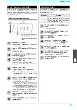
Page 48: ... key instead of the END POWER key the value entered here will be invalid 4 Press the key several times to end the setting Be sure to perform feed correction each time before printing The media feed amount may vary depending on the remaining amount of the roll media If use by setting the media to Narrow roll holder rewind the roll media by hand and set without slack There may not be accurate to cor...

Page 49: ...rn 2 in the order of printing 6 Press to enter a correction value of Pattern 1 and press the key Corrected feeding rate 40 to 40 Check the test patterns The position where an outward feeding line and a return feeding line become one straight line is the correction value When the correction value in not between 40 and 40 adjust the height of the printing heads and then perform the operations in Ste...

Page 50: ...Press the LOCAL during printing The printing operation stops Interrupt data sending at the PC side during the data is sent from the PC Printing restarts from the interrupted data by repressing the REMOTE key Deleting Received Data Data Clear When you want to stop printing delete the already received data 1 Press the key and press the DATA CLEAR in LOCAL 2 Press the key The received data is erased ...

Page 51: ...le 3 13 Setting a AUTO Power off 3 13 Setting Feeding unit 3 13 Setting Take up unit 3 13 Setting the Display of Media Remain 3 14 Setting Time 3 14 Setting Unit Temperature Length 3 14 Setting a Key Buzzer 3 15 Setting the Display of Media Detection 3 15 Setting the CONFIRM FEED 3 15 Initializing the Settings 3 16 About Nozzle Check MENU 3 17 Nozzle Check MENU table 3 17 Printing Check Flow 3 18 ...

Page 52: ...Pos Correct are performed the ADJUST MENU can be displayed easily without selecting MENU Setup from Local Press the SEL key to display ADJUST for FUNC1 and then press the FUNC1 key Press this to select SETTING MENU or to switch to the previous screen Press this to use the adjust function Press this to switch to the next screen Use these to select a setting item Press this to confirm a setting etc ...

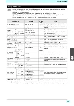
Page 53: ...s the movement time until the head heater and ink heater standby status Logical Seek P 3 6 Data Media Quality Sets the scan movable area during printing Overprint P 3 6 Host 1 to 9 1 Sets the number of layers in which ink is to be applied Margin L P 3 7 10 to 0 to 85mm Sets a non printing area along the right and left edges of the media Margin R P 3 7 UV Mode P 3 7 AUTO Adjust 50 to 0 to 50 Adjust...

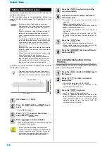
Page 54: ...cted in the corrected feeding rate soon 3 Press the key twice key The changed value is registered When you press the ENTER key instead of the END POWER key the value entered here will be valid temporarily When you perform media detection again or turn the power OFF the correction value is cleared Be sure to perform feed correction each time before printing The media feed amount may vary depending ...

Page 55: ...t line is the correction value When the correction value in not between 40 and 40 adjust the height of the printing heads and then perform the operations in Step 2 and later 7 In the same way as in Step 6 enter a correction value of Pattern 2 and press the key 8 Press the key several times to end the setting Setting the Heater This machine is equipped with a pre heater on its backside and contains...

Page 56: ...o 9 times 5 Press the key several times to end the setting If the Logical Seek is set to Data or Media the following phenomena may occur In such a case set the Logical Seek to Quality The accuracy of the media feed amount is lowered Media skews Lateral stripes occur due to feed variations UNI DIRECTIONAL BI DIRECTIONAL Movement of heads when Logical Seek is Media Movement of heads when Logical See...

Page 57: ...vice and press the key Set value 50 to 50 If you set this value to 0 the machine applies an intensity recommended for each of the printing modes Setting a negative value reduces the intensity setting a positive value increases the intensity 8 Press the key several times to end the setting If you fail to adjust the amount of light in the AUTO settings 1 Press the MENU key in Local SETUP MENU appear...

Page 58: ... of ink curing first and increase the value to strengthen the curing level and decrease the level to weaken the curing level 11 Press the key several times to end the setting UV Mode Setup Procedure Example To weaken the curing level in bi directional printing 1 In the AUTO settings set Light Adjust in the negative direction 2 Even when 50 is set for Light Adjust if the ink curing level is strong ...

Page 59: ...ess to select a set value and press the key Set value Host Weak Standard Strong OFF 5 If you choose any other option than OFF in step 4 press choose whether to constantly operate the vacuum fan and press the key ON Vacuum fan is constantly on OFF Vacuum fan is only on when printing or performing jog operation 6 Press the key several times to end the setting Setting of Print Speed Changes the media...

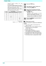
Page 60: ...nd press the key 4 Press to select the type of auto cleaning and press the key There are File Length and Time for auto cleaning File When the set files has been completed the machine performs head cleaning automatically Length When the set length has passed the machine performs head cleaning automatically Time When the set time has passed the machine performs head cleaning automatically If you do ...

Page 61: ...ccurred set the interval between each operation shorter 1 Press the MENU key in Local SETUP MENU appears 2 Press the 3 Press to select Interval Wiping and press the key 4 Press to set intervals Set Value 3 to 255 Minutes OFF When OFF is set periodical wiping is not executed 5 Press the key 6 Press the key several times to end the setting The color tone may change depending on the timing when perio...

Page 62: ...ine easily The following items can be set in Machine settings Press this to select Machine Setup MENU or to switch to the previous screen Press this to switch to the next screen Use these to select a setting item Press this to confirm a setting etc Machine Setup MENUs at a glance ...

Page 63: ...s the key several times to end the setting Function name Set value Default Meaning AUTO Power off P 3 13 NONE 10 600min 30min When no operation has been performed for the set time the power supply is automatically turned OFF Feeding Unit P 3 13 ON OFF ON You can set the operation method when the ON OFF button on the take up unit is pressed Take up Unit P 3 13 ON OFF ON You can set the operation me...

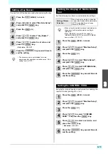
Page 64: ...ss to select Unit Temp or Unit Length and press the key 5 Press to select a set value and press the key Set value of tempture C F Set value of length mm inch 6 Press the key several times to end the setting When the media remaining amount display is turned to ON the remaining amount of a media is displayed in Remote However when a leaf media is used the length of the media to be printed is display...

Page 65: ...to end the setting Setting the CONFIRM FEED Set whether media feeding is performed for checking the result of the test printing etc or not 1 Press the MENU in Local 2 Press to select Machine Setup and press the key 3 Press the 4 Press to select CONFIRM FEED and press the key 5 Press to select a set value and press the key Set value ON OFF 6 Press the key several times to end the setting The buzzer...

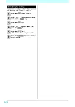
Page 66: ...achine Setup to the status before shipment 1 Press the MENU in Local 2 Press to select Machine Setup and press the key 3 Press the 4 Press to select Reset and press the key 5 Press the key The already configured settings are initialized 6 Press the key several times to end the setting ...

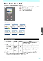
Page 67: ...missing during printing set whether to continue or stop the print Action Cleaning Soft Normal Hard Soft Sets the type of cleaning performed during recovery work Retry Count 0 to 3 1 Repeats the retry operation for the set number of times Auto Nozzle Recoverry P 3 19 ON OFF OFF Set this when you want to conduct automatic nozzle recovery Maximum 16 per 1 nozzle line 2 2 Depending on the print condit...

Page 68: ...ings are enabled 1 nozzle check Judgment 2 3 Recovery operation nozzle check Judgment 4 Retry Judgment Printing Check Judgment Detects missing nozzles If more missing nozzles than Judgement Condition are detected after the nozzle check cleaning is performed and nozzle check is conducted again 5 Nozzle Missing judgment If more missing nozzles than A are eventually detected continued printing will b...

Page 69: ...the key 10 Press to select Continuation Print and press the key 11 Press to select setting value and press the key Setting value Stop Continue 12 Press to select cleaning type and press the key 13 Press to select setting value and press the key Setting value Soft Normal Hard 14 Press to select retry count and press the key Setting value 0 to 3 15 Press the key several times to end the setting Sett...

Page 70: ...can be confirmed The following items can be confirmed as machine information Press this to select Information MENU or to switch to the previous screen Press this to switch to the next screen Use these to select a setting item Press this to confirm a setting etc ...

Page 71: ...nformation Menu is displayed 1 Press the FUNC1 MENU in Local 2 Press to select Information and press the ENTER key twice 2 Press to select UV LAMP and press the key The use time is displayed for each of the UV lamps Item Description USAGE WIPING This displays how many wipings have been done PRINT Length This displays the total length of the printing done to date PRINT AREA This displays the total ...

Page 72: ...l Setting a Language You can change the displayed language 1 Press the MENU key in Local Language MENU appears 2 Press to select language and press the key Set Value 日本語 English Español Português 中文 3 Press the key several times to end the setting Ink information Error Warning Only at the time of occurrence Machine information Media width Serial No Version Nozzle recovery Only at the time of regis...

Page 73: ...er and Cap 4 7 Washing the Ink Discharge Passage 4 9 When the Machine Is Not Used for a Long Time Custody Wash 4 10 Cleaning the Ink Head and the Area around It 4 12 When nozzle missing Cannot Be Solved 4 13 Washing the Head Nozzle 4 13 Nozzle Recovery Function 4 14 Automatic Maintenance Function 4 16 Setting the Refreshing level 4 16 Setting the Cleaning level 4 16 Discarding waste ink 4 17 For w...

Page 74: ... shock hazards or damage to the machine To ensure stable ink jetting it is necessary for the machine to eject a small amount of ink flushing regularly when a printing outputting operation has not been performed for a long time When the machine is not to be used for a long time turn off only the power button on the front side leave the main power switch at the side turned ON in the position of and ...

Page 75: ...overed with dust etc it may cause false detection of media Using a cotton swab remove the dust etc accumulated on the surface of the sensor When cleaning the sensor on the lower surface of the head is cleaned move the carriage to the left end by the operations of step 1 of P 4 12 Cleaning the Ink Head and the Area around It and clean it Before cleaning the cover be sure to check that the pre heate...

Page 76: ...ticks to the nozzles which may result in abnormal printing Clean the media press regularly with a dry cloth or paper towel If there is ink on the media press wipe it away with a clean stick dipped in washing liquid for maintenance When using washing liquid for maintenance be sure to wipe it away completely so that none remains on the media press Media press ...

Page 77: ... can be displayed easily without selecting MENU Maintenance from Local Press the SEL key to display TEST PRINT CLEANING for FUNC2 and then press the FUNC2 key Press this to select Maintenance MENU or to switch to the previous screen Press this to use the maintenance function Press this to switch to the next screen Use these to select a setting item Press this to confirm a setting etc Maintenance M...

Page 78: ... is managed in this device is reset Nozzle Recovery P 4 14 For printing using another nozzle if nozzle wash and so forth fail to effect recovery from nozzle missing etc PRINT Used to print a pattern and to check and or register clogged nozzles ENTRY Registers the faulty nozzle identified by PRINT CLEAR Resets a registered faulty nozzle CHECK Checks recoverable printable conditions Auto Maint P 4 1...

Page 79: ...o the front 3 While pulling the right side maintenance cover downward remove it If the right side maintenance cover is hard to remove use the supplied screwdriver 6 Remove the wiper Pull out the wiper by holding the protrusions at its both ends Tools required for Maintenance Washing liquid for maintenance SPC 0568 Clean stick SPC 0527 Gloves Goggles Be sure to wear the supplied goggles and gloves ...

Page 80: ...ubber cover Wipe off the ink sticking to the cap rubber and cap rubber cover with a clean stick dipped in cleaning solution for maintenance Wipe off so that cleaning solution for maintenance will not remain 11 Close the right side maintenance cover then press the key After its initial operation the machine returns to step1 Performing the Station without FUNC2 TEST PRINT CLEANING key You can select...

Page 81: ...hing work is completed 4 Open the right side maintenance cover 1 Rotate the screws under the right side maintenance cover for two positions to the left and remove them 2 Hold the bottom of the right side maintenance cover and pull it to the front 3 While pulling the right side maintenance cover downward remove it If the right side maintenance cover is hard to remove use the supplied screwdriver 5 ...

Page 82: ...s at both ends of the wiper 2 Clean the wiper and bracket with a clean stick dipped in maintenance washing liquid for maintenance SPC 0568 Washing liquid for maintenance Wipe off so that maintenance washing liquid for maintenance will not remain 3 Insert it in the original position by holding the projections at both ends of the wiper 6 Clean the cap rubber and cap rubber cover and press the key Wi...

Page 83: ...zles are washed When the nozzles have been completely washed the head moves onto the platen 9 Suction the cleaning solution into a syringe and squirt about three syringes worth of solution into each cap 10 Close the right side maintenance cover and press the key After the idle absorbing operation has been performed for 30 seconds the screen returns to step2 Until washing liquid is filled Fill the ...

Page 84: ...eft side maintenance cover is hard to remove use the supplied screwdriver 6 Wipe ink sticking to the side of the head off with a clean stick Never rub the nozzles 7 Clean the bottom surface of the UV lamp If there is any ink stuck on the rear side of the bottom surface of the UV lamp apply the cleaning solution for maintenance to a clean stick and wipe the ink away Wipe off so that cleaning soluti...

Page 85: ... remove it If the right side maintenance cover is hard to remove use the supplied screwdriver 5 Clean the wiper and the bracket and press the key 1 Pull out it by holding projections at both ends of the wiper 2 Clean the wiper and bracket with a clean stick dipped in maintenance washing liquid for maintenance SPC 0568 Washing liquid for maintenance Wipe off so that maintenance washing liquid for m...

Page 86: ...nting Print the nozzle pattern Used to print a pattern and to check and or register clogged nozzles 1 Press the MENU in Local 2 Press to select Maintenance and press the key Maintenance MENU appears 3 Press to select Nozzle Recovery and press the key 4 Press the key 5 Press to select desired head s H1 2 H3 4 and press the key 6 Press the key twice Printing of the nozzle pattern will start Select E...

Page 87: ... 4 Press to select CHECK and press the key The mode for which nozzle recovery is invalid is displayed If there is no mode for which nozzle recovery is invalid NONE is displayed 5 Press the key several times to end the setting Head No H1 to H2 Nozzle line Recovery nozzle No or OFF Registration number 1 to 10 Nozzle missing No 184 Nozzle number Nozzle missing No 16 Nozzle missing No 128 Registration...

Page 88: ...ress the key 4 Press the key Refresh will be selected 5 Press to set the refresh level and press the key Set value OFF Lv 1 Lv 2 Lv 3 6 Press the key several times to end the setting Setting the Cleaning level The head cleaning level is set 1 Press the MENU in Local 2 Press to select Maintenance and press the key Maintenance MENU appears 3 Press to select Auto Maint and press the key 4 Press to se...

Page 89: ...red or overflow When disposing of the waste ink be sure to wear attached goggles and gloves to perform the work Otherwise you may get ink in your eyes If you get the ink on your skin or in your eyes wash it away with plenty of water immediately When pulling out the tube ink may drop from the tip of the tube Wipe the tube with waste cloth and cover the tip before starting work Request the treatment...

Page 90: ...oon as possible Dispose of waste ink according to regional laws and regulations Following operations will not be activated Operation using ink Print Remote transition If occurs during printing transit to local after printing completion Emptying the waste ink tank referring to the manual Chapter 4 Discarding waste ink Then please reset the waste ink tank Dispose of waste ink according to regional l...

Page 91: ...guideline The amount may be different from the amount acutally accumulated 1 Press key twice to display the WASTE INK to FUNC2 2 Press WASTE INK 3 Press to adjust the amount of waste ink Adjust to match the actual amount of waste ink 4 Press key Set to 0 Set to 10 Set to 30 Set to 50 Set to 70 ...

Page 92: ...r was used is reset 6 Open the rght maintenance cover then remove the wiper Pull out the wiper by holding the protrusions at its both ends 7 Insert a new wiper Insert a new wiper by holding its both ends There is no direction to the wipers They can be inserted with either side facing forward 8 Close the right side maintenance cover and press the key After its initial operation the machine returns ...

Page 93: ...intenance cover downward remove it If the right side maintenance cover is hard to remove use the supplied screwdriver 5 Remove the H fan filter cover at the right side of the carriage Remove the screw on the H fan filter cover before removing the cover 6 Remove the used H fan filter cover 7 Mount a new H fan filter SPC 0766 Align the hole in the H fan filter with the screw hole 8 Return the H fan ...

Page 94: ...g area with waste cloth for protection against dirt before changing the ink tank 1 Remove the ink filter attached to the ink tank Loosen the joints on the top of the ink filter and remove the filter 2 Remove the ink tank Take care not to tilt the ink tank greatly when removing the tank It may cause ink leakage from the cap 3 Set a new ink tank and mount the ink filter Tighten the joints on the top...

Page 95: ...er 1 Rotate the screws under the right side maintenance cover for two positions to the left and remove them 2 Hold the bottom of the right side maintenance cover and pull it to the front 3 While pulling the right side maintenance cover downward remove it If the right side maintenance cover is hard to remove use the supplied screwdriver 5 Remove the plates front and rear retaining the absorber 6 In...

Page 96: ...u make mixed water The mixed water that one week or more passed after it makes it is never used for this machine regardless of use unused Moreover do not add to the mixted water newly made Cooling device Be sure to wear goggle and gloves for handling the antifreeze liquid Use the recommended antifreeze liquid SPC 0394 by Mimaki If not the cooling device may be broken Supplied antifreeze liquid 100...

Page 97: ... syringe 2 Uncover the feed water inlet and the air vent 3 Refill antifreeze mixed water Fill the antifreeze mixed water from the feed water inlet Fill it up seeing the water gauge on the back of this machine Displaying red on the water gauge indicates full 4 Close the feed water inlet and the air purge cover Be aware that if you put in too much antifreeze mixed water it may leak from the cooling ...

Page 98: ...4 26 ...

Page 99: ... 2 The machine does not start printing 5 2 Media get jammed media is soiled 5 3 Image quality is poor 5 3 Nozzle is clogged 5 3 Ink tank warning appears 5 4 If an error related to the Sub Tank occurs Error 618 to 61b 5 4 If nozzle missing due to color mixture of ink or aeration 5 4 When media heaves up at feeding 5 6 Warning Error Messages 5 7 Warning messages 5 7 Error messages 5 12 Chapter 5 Tro...

Page 100: ...ed to the machine properly It can also occur when the printing function does not work properly or the media is not set correctly Has the power cable been connected between the machine and a power plug socket Securely connect the power cable Is the main switch ON Turn on the main switch P 2 3 Is the power button located on the front of machine ON Turn on the power button on the front of the machine...

Page 101: ...r bent ends Yes Is the height of the head proper Adjust the distance between the media and the head will be 1 5 mm to 2 mm P 2 4 Yes Is the media hanging down along the platen Use a take up device P 2 7 step 11 or re load the media on the machine P 2 4 Open the front cover and raise the clamp lever Remove the clogged media Close the front cover Phenomenon Measures White lines blur dark stripes in ...

Page 102: ...mpleted to perform head cleaning If nozzle missing due to color mixture of ink or aeration If nozzle missing occurs due to color mixture of ink in the head or aeration push ink or air in the head out from the port 1 Press the MENU in Local 2 Press to select Maintenance and press the key Maintenance MENU appears 3 Press to select Air PG and press the key The station moves downward to the empty abso...

Page 103: ...11 Make sure the display of Please wait is off from the display 12 Remove the jig from the ink port and cap the ink port It is recommended to remove the jig in the micropositive pressure status to prevent ink from spouting The machine supplies ink into the sub tank containing less ink Wait for a while until the display changes To continue work follow the steps 10 and 11 13 Press to select RETRY or...

Page 104: ...media is set straight and reset it Adjusting heater temperature 1 Upper pre heaters temperatures Media feeding 1 For roll media feed the media by about tens of centimeters to one meter 2 For leaf media press and perform feed back feed Do not leave the media in the heater warming status 1 Do not start printing with the media cockled because it may cause media jam Heighten the head 1 For the thick m...

Page 105: ... date WRONG INK IC CANNOT CHARGE The IC chip cannot be read normally Remove the IC chip and insert it again INK IC ALREADY USED CANNOT CHARGE An IC chip that has already been charged was inserted Install the new IC chip INK TYPE CANNOT CHARGE The type of ink on the inserted IC chip is different from the ink in the bottle Check the type of ink on both the IC chip and the ink bottle INK COLOR CANNOT...

Page 106: ...TNK SENS MCYK Detected an abnormality of the ink tank sensor Make sure the ink supply unit is con nected to the machine Check if any weight or load is taken on the ink tank Implement the Tank Calibration of the maintenance menu and perform the cor rection of the balance If the same error message appears again contact a distributor in your district our office or our call center to call Calibration ...

Page 107: ...ect the abnormality in the take up ten sion bar Check the set state of the media and take a problem Check if the taking up direction switch is set correctly Take UP Voltage Abnormal voltage of the take up motor Turn off the main power to the machine and turn it on after a while Even if you perform if the same message is displayed contact a distributor in your district our office or our call center...

Page 108: ...r occurred during nozzle check printing was stopped and the nozzle check function was turned OFF NCU CENTER POS Nozzle check OFF NCU SN ADJST Nozzle check OFF NCU NZK CHK HW Nozzle check OFF NCU NZK CHK MARK Nozzle check OFF NCU CONNECT The NCU unit is not connected The nozzle check function cannot be used Turn off the main power to the machine and turn it on after a while Even if you perform if t...

Page 109: ... machine is cold Use a heating system to raise the room temperature to a specified range Wait until the machine warms up Even if you perform if the same message is displayed contact a distributor in your district our office or our call center Cover Open Detected cover open Check the cover front cover right main tenance cover left maintenance cover close the cover if open and press the ENTER key If...

Page 110: ...ER ERROR 128 BATTERY EXCHANGE The battery life end of the internal clock is detected Contact your local distributor to call for service ERROR 12a HDC SPEED 12 Ink discharge control error Turn off the power button to the machine and turn it on after a while If the same error message appears again contact your local distributor to call for service ERROR 12a HEAD ROM WR Head control error ERROR 12e H...

Page 111: ...le connection Use a USB cable conforming to the standard Check output conditions ERROR 304 USB INIT ERR USB device error Turn off the power button to the machine and turn it on after a while If the same error message appears again contact your local distributor to call for service ERROR 305 USB TIME OUT ERROR 306 USB GET DESC ERROR 401 MOTOR X An excessive load was applied to the X motor ERROR 402...

Page 112: ...itch are set correctly Check that the media can be taken up to the feeding unit Check if the media feeding paper core is running without load Turn ON and OFF the manual switch and raise the tension bar to a correct position Feed the media in the jog operation in the direction reverse to that used at the time when the error occurred ERROR 427 Take UP Cover OPEN It was detected that the media take u...

Page 113: ...CK Abnormal linear scale Turn off the power button to the machine and turn it on after a while If the same error message appears again contact your local distributor to call for service ERROR 516 MEDIA SET POSITION R The media is set outside the proper area Check the media set position ERROR 516 MEDIA SET POSITION L ERROR 531 INKTNK SENS MCYK The weight balance is abnormal Make sure the ink supply...

Page 114: ...3 NCU NZK CHK MARK ERROR 654 NCU CENTER POS Adjustment of the discharge position to the NCU has failed ERROR 655 NCU FLUSH POS ERROR 656 NCU SN ADJST Sensor sensitivity adjustment has failed ERROR 657 REPLACE NCU INK PAD The NCU ink pat is full Contact our service desk or your local distributor to call for service ERROR 658 NCU SENSOR LV LOW The NCU sensor sensitivity is falling Replacement of the...

Page 115: ...e power button to the machine and turn it on after a while If the same error message appears con tact our service desk or your local distrib utor to call for service ERROR 718 InkHeaterPCB Thr 1234 The thermistor on the ink heater relay board is defective ERROR 719 InkHeaterPCB Fuse 1234 The fuse on the ink heater relay board was blown ERROR 71a UV DRV Fuse 0 0 The fuse on the UV DRV board was blo...

Page 116: ...5 18 Chapter 5 Troubleshooting ...

Page 117: ...the lists of the specifications and functions of this machine Specifications 6 2 Machine specifications 6 2 Ink specifications 6 3 Supply item list 6 3 Setting orders of ink tanks 6 4 Sheet for inquiry 6 5 Chapter 6 Appendix ...

Page 118: ...ches Printing surface Regardless of inside and outside Roll end treatment The roll end is gently fixed to the core with weak adhesive tape or weak glue for easy removal Leaf media size Maximum 3250mm Minimum 210mm Margin Leaf media Left end and right end 15 mm Default Front 1400 mm Rear 1300 mm Roll media Left end and right end 15 mm Default Front 1600 mm Rear 1300 mm Distance accuracy Reproducibi...

Page 119: ...capacity 1 liter Shelf life The period is printed on the ink bottle Within three months after opening the package even in the available period Storage tempera ture Storage 5 to 30 C Transportation 1 to 60 C Storage at temperature of 60 C is only permitted within 120 hours and at temperature of 40 C is permitted within a month Do not disassemble the ink bottle Ink could freeze if kept in a cold pla...

Page 120: ...ting orders of ink tanks The setting value and the setting orders of the ink tanks differ depending on the ink type you use Refill the ink matching the label Do not refill the ink different in color from the label Label Bk Y C M ...

Page 121: ...ll in the following necessary items and fax the sheet to our sales office Company name Person in charge Telephone number machine model Operating OS Machine information 1 1 Refer to Confirming Machine information of About Information MENU then fill in necessary information P 3 20 Error message Contents of inquiry ...

Page 122: ...Chapter 6 Appendix 6 6 ...

Page 123: ...SIJ 320UV Operation Manual August 2016 MIMAKI ENGINEERING CO LTD 2182 3 Shigeno otsu Tomi shi Nagano 389 0512 JAPAN D202809 13 31082016 ...

Page 124: ...MM FW 1 50 MIMAKI ENGINEERING CO LTD 2015 ...

Reviews: