Section 3-7
Alarm and Control Unit
Page 3-7-2
11/18/03
CM 100Base-T System User’s Manual
The Status and Control Extender (SCE) and the Network Management System (NMS)
interface the radio through the ACU.
Since ACU faults do not affect radio data traffic, the ACU, part number MLN7195, sits in
the SP shelf without a redundant unit. The optional Network Management Unit (NMU)
daughter board sits on top of the ACU (Chapter 3, Section 3-16).
Functional Description
The CM system software, MVN4025, resides on the ACU in a programmable IC.
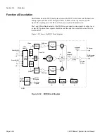
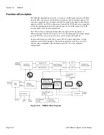
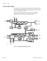
Performance signals from all radio modules, Figure 3-7-2, go to the ACU for comparison
to criteria in the system software. Signals that do not match set criteria are alarm
conditions. The ACU also receives and logs alarms that individual radio modules
generate.
When the ACU verifies an alarm condition it sends a signal to the module to light its
alarm LED. The alarm condition may also cause the ACU to initiate a path protection
switch. Counters in the ACU monitor FEC and parity error signals from the MUX to
determine when to start adaptive power control, perform a path protection switch, and to
calculate the bit-error rate.
The ACU maintains a 512-event history, called the Alarm Log, and a seven-day
performance log of the radio performance statistics. Access the performance log, event
history, and manual controls through QuikLink; the local maintenance interface
(Appendix B) or through the Network Management application.
ACU
Processor
ADC = analog-to-digital converter
P I/O = parallel input / output
S I/O = serial input / output
F-0775
ADC
Analog from all Modules
P I/O
Alarms from all Modules
P I/O
LED Control to all Modules
Counter
Parity Errors
FEC Errors
Control Communications Channel
S I/O
S I/O
ACU-ACU Communications Channel
S I/O
Local Display Unit RS232
S I/O
Status and Control Extender Panel
RS 232
S I/O
Comm. Channel to NM Processor
Figure 3-7-2. ACU Block Diagram
Summary of Contents for CM7
Page 2: ......
Page 4: ...Page iv 5 04 05 CM7 8 100Base T System User s Manual ...
Page 16: ...Glossary Page xvi CM System Users Manual X Y Z ...
Page 24: ...Microwave Networks CM7 8 100Base T System User s Manual Pagexxiv ...
Page 62: ...Chapter 2 Operation Page 2 18 5 02 05 CM 100Base T System User s Manual ...
Page 64: ...Chapter 3 Module Descriptions Page 3 2 CM7 8 100Base T ...
Page 88: ...Section 3 3 Transmitter Unit Page 3 3 6 CM7 8 System User s Manual ...
Page 96: ...Section 3 5 RF Power Supply Unit Page 3 5 4 CM System User s Manual ...
Page 100: ...Section 3 6 SP Power Supply Unit Page 3 6 4 CM System User s Manual ...
Page 106: ...Section 3 7 Alarm and Control Unit Page 3 7 6 11 18 03 CM 100Base T System User s Manual ...
Page 124: ...Section 3 11 SYNDES Page 3 11 6 CM System User s Manual ...
Page 130: ...Section 3 12 SCU Page 3 12 6 11 18 03 CM 100Base T System User s Manual ...
Page 138: ...Section 3 13 OWU Page 3 13 8 CM System User s Manual ...
Page 150: ...Section 3 15 NMU Page 3 15 6 CM System User s Manual ...
Page 192: ...Chapter 5 Verification Page 5 20 CM System User s Manual ...
Page 194: ...Chapter 6 Maintenance Page 6 2 7 23 03 CM 100Base T System User s Manual ...
Page 224: ...Chapter 6 Maintenance Page 6 32 7 23 03 CM 100Base T System User s Manual ...
Page 226: ...Site Engineering Page 2 CM System User s Manual ...
Page 230: ...Appendix A T I Curves Page A 4 CM7 8 100Base T System User s Manual ...
Page 267: ...Microwave Networks CM System User s Manual PageB 37 ...
Page 268: ...Appendix B QuikLink Page B 38 CM System User s Manual ...
Page 282: ...Appendix D Alarm Codes Page D 6 5 02 05 CM 100Base T System User s Manual ...
Page 290: ...Appendix E Setting Frequency Page E 8 CM7 8 System User s Manual ...
Page 312: ...CM7 8 100Base T System User s Manual Page I 4 Microwave Networks ...


