Microwave Networks
CM7/8 System User’s Manual
Page 3-4-3
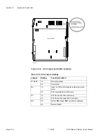
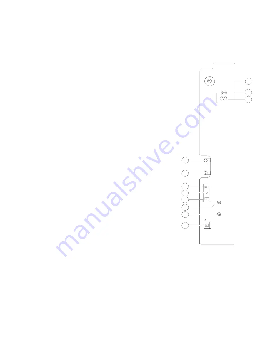
Front Panel Features
Refer to Figure 3-4-3 for the locations of the following indicators, controls, and test
points:
1.
RF IN - SMA connector that accepts in-
put signal between -77 dBm and -25 dBm
at the receive frequency.
2.
LO FREQ ADJ - DIP switch for coarse-
adjust of the LO frequency. May be used
to increase LO FREQ ADJ potentiometer
range.
3.
LO FREQ ADJ Capacitor- Fine-adjusts
the LO frequency, and therefore, the re-
ceive frequency.
4.
IF OUT - SMA interface that supplies the
70 MHz IF signal at -10 dBm to the DE-
MOD.
5.
LPBK LO IN - SMA connector that re-
ceives the first conversion LO signal
from the adjacent TXU for RF local loop-
back test.
6.
AGC MON - Test point for AGC voltage
(RSL).
7.
RX ALM - Red LED controlled by the
ACU that indicates the RXU is in alarm.
8.
GND - Test point ground connection.
9.
LO MON - SMA interface that is a sam-
ple of the LO signal for monitoring. The
signal level is -5 dBm. The LO frequency
is equal to the receive frequency ±70
MHz.
10. TX LO OUT - SMA interface that con-
nects the LO signal from the synthesizer
to the associated TXU.
11. RF LPBK - Switch to configure the RXU
for RF local loopback operation.
F-1162
RF IN
RXU
AGC MON
RF LPBK
LO FREQ
ADJ
LPBK LO IN
IF OUT
RX ALM
GND
LO MON
TX LO OUT
OFF
1
2
3
4
5
6
7
8
11
9
10
Figure 3-4-3. RXU Features
Summary of Contents for CM7
Page 2: ......
Page 4: ...Page iv 5 04 05 CM7 8 100Base T System User s Manual ...
Page 16: ...Glossary Page xvi CM System Users Manual X Y Z ...
Page 24: ...Microwave Networks CM7 8 100Base T System User s Manual Pagexxiv ...
Page 62: ...Chapter 2 Operation Page 2 18 5 02 05 CM 100Base T System User s Manual ...
Page 64: ...Chapter 3 Module Descriptions Page 3 2 CM7 8 100Base T ...
Page 88: ...Section 3 3 Transmitter Unit Page 3 3 6 CM7 8 System User s Manual ...
Page 96: ...Section 3 5 RF Power Supply Unit Page 3 5 4 CM System User s Manual ...
Page 100: ...Section 3 6 SP Power Supply Unit Page 3 6 4 CM System User s Manual ...
Page 106: ...Section 3 7 Alarm and Control Unit Page 3 7 6 11 18 03 CM 100Base T System User s Manual ...
Page 124: ...Section 3 11 SYNDES Page 3 11 6 CM System User s Manual ...
Page 130: ...Section 3 12 SCU Page 3 12 6 11 18 03 CM 100Base T System User s Manual ...
Page 138: ...Section 3 13 OWU Page 3 13 8 CM System User s Manual ...
Page 150: ...Section 3 15 NMU Page 3 15 6 CM System User s Manual ...
Page 192: ...Chapter 5 Verification Page 5 20 CM System User s Manual ...
Page 194: ...Chapter 6 Maintenance Page 6 2 7 23 03 CM 100Base T System User s Manual ...
Page 224: ...Chapter 6 Maintenance Page 6 32 7 23 03 CM 100Base T System User s Manual ...
Page 226: ...Site Engineering Page 2 CM System User s Manual ...
Page 230: ...Appendix A T I Curves Page A 4 CM7 8 100Base T System User s Manual ...
Page 267: ...Microwave Networks CM System User s Manual PageB 37 ...
Page 268: ...Appendix B QuikLink Page B 38 CM System User s Manual ...
Page 282: ...Appendix D Alarm Codes Page D 6 5 02 05 CM 100Base T System User s Manual ...
Page 290: ...Appendix E Setting Frequency Page E 8 CM7 8 System User s Manual ...
Page 312: ...CM7 8 100Base T System User s Manual Page I 4 Microwave Networks ...