


Microwave Networks
CM System Users Manual
Page B-31
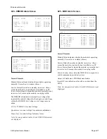
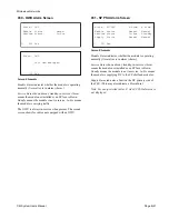
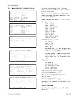
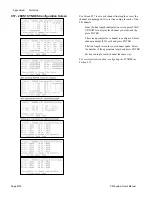
070 - Control and Maintenance Menu
Menu Selections
Item 1 sets path switching on the TXU-MOD, RXU-
DEMOD, MUX-SYNDES, SCU, and WTU switch planes
to on or off, and lock (manual) or automatic.
Item 2 sets loopback for IF (baseband on Telestar radios,)
MUX, SYNDES, SCU, WTU, and clears all loopbacks.
Item 3 toggles APC on or off manually, or sets APC to
automatic.
Item 4 toggles power amplifiers on or off.
Item 5 sets the monitor and controls for the ACU/NMU
external TTL and relay inputs and outputs.
Note: Items 1 and 2 are not used on non-protected systems.
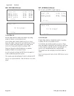
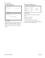
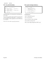
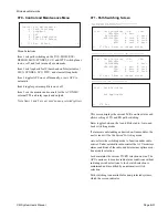
071 - Path Switching Screen
This screen displays the current Tx/Rx on-line status and
allows setting of TX and RX path switching.
Enter toggles between the A and B side radio, Auto, and
Lock switching modes.
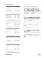
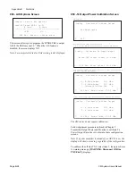
If alarms are outstanding on desired on-line modules, the
next screen will be the
Forced Switching
menu.
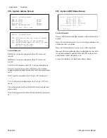
Auto
selects the switching mode to function under radio
control. Under automatic radio control the ACU monitors
alarm conditions of the radio and determines optimum on-
line module selection.
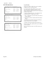
Lock
maintains the current TX/RX selection on-line. The
ACU continues to monitor radio alarm conditions without
initiating switch selections. A lock switch selection is
maintained until modified by an automatic switch
selection.
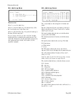
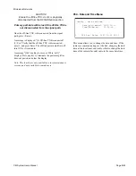
Path switching is unavailable for non-protected systems,
which the screen indicates.
L 070 Esc Select_ o
Control and Maintenance
>1. Path Switching
2. Loopback
3. APC
4. Power Amplifiers
5. TTL I/O & Relays
L 071 Esc Enter to change states
Ctrl - Path Switching -TX- -RX-
TXU-MOD: >A Auto
RXU-DEMOD: A Auto
MUX-SYNDES: B Lock A Lock
SCU: A Lock B Lock
WTU: A Lock B Auto
L 071 Esc Enter to change states
Ctrl - Path Switching -TX- -RX-
TXU-MOD: - ----
RXU-DEMOD: A Auto
MUX-SYNDES: >A Auto A Lock
SCU: A Auto B Lock
WTU: A Lock B Lock
L 071 Esc
Ctrl - Path Switching
Not Applicable
Hot-Standby and Space Diversity Protection
(HH and HS) Configurations
Frequency Diversity Protected (FF) Configuration
Non-Protected (NN) Configuration
Summary of Contents for CM7
Page 2: ......
Page 4: ...Page iv 5 04 05 CM7 8 100Base T System User s Manual ...
Page 16: ...Glossary Page xvi CM System Users Manual X Y Z ...
Page 24: ...Microwave Networks CM7 8 100Base T System User s Manual Pagexxiv ...
Page 62: ...Chapter 2 Operation Page 2 18 5 02 05 CM 100Base T System User s Manual ...
Page 64: ...Chapter 3 Module Descriptions Page 3 2 CM7 8 100Base T ...
Page 88: ...Section 3 3 Transmitter Unit Page 3 3 6 CM7 8 System User s Manual ...
Page 96: ...Section 3 5 RF Power Supply Unit Page 3 5 4 CM System User s Manual ...
Page 100: ...Section 3 6 SP Power Supply Unit Page 3 6 4 CM System User s Manual ...
Page 106: ...Section 3 7 Alarm and Control Unit Page 3 7 6 11 18 03 CM 100Base T System User s Manual ...
Page 124: ...Section 3 11 SYNDES Page 3 11 6 CM System User s Manual ...
Page 130: ...Section 3 12 SCU Page 3 12 6 11 18 03 CM 100Base T System User s Manual ...
Page 138: ...Section 3 13 OWU Page 3 13 8 CM System User s Manual ...
Page 150: ...Section 3 15 NMU Page 3 15 6 CM System User s Manual ...
Page 192: ...Chapter 5 Verification Page 5 20 CM System User s Manual ...
Page 194: ...Chapter 6 Maintenance Page 6 2 7 23 03 CM 100Base T System User s Manual ...
Page 224: ...Chapter 6 Maintenance Page 6 32 7 23 03 CM 100Base T System User s Manual ...
Page 226: ...Site Engineering Page 2 CM System User s Manual ...
Page 230: ...Appendix A T I Curves Page A 4 CM7 8 100Base T System User s Manual ...
Page 267: ...Microwave Networks CM System User s Manual PageB 37 ...
Page 268: ...Appendix B QuikLink Page B 38 CM System User s Manual ...
Page 282: ...Appendix D Alarm Codes Page D 6 5 02 05 CM 100Base T System User s Manual ...
Page 290: ...Appendix E Setting Frequency Page E 8 CM7 8 System User s Manual ...
Page 312: ...CM7 8 100Base T System User s Manual Page I 4 Microwave Networks ...


