


CM System User’s Manual
6/14/02
Page F-7
Microwave Networks
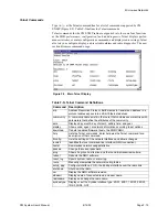
Local Access Port
The DB9 local access connection provides a 9600-bps serial interface to the NMU
from a VT100 compatible terminal for local configuration. The ACU shares this port
with the NMU. NMU switch SW1-6 sets which unit uses the port. With SW1-6 OPEN
the ACU controls the local access port and when CLOSED the NMU controls the port.
The female local-access port connector carries three RS-232 compatible signals as
Table F-I describes. Set the terminal to 9600, 8, N,1 with no flow control to communi-
cate with the NMU.
The opposite end of a serial cable connects a computer or terminal serial port to the
local access connector. The computer uses either a DB9 connector (9-pin) or a DB25
(25-pin) connector. For a computer with a DB9 connector, strap pins 7 and 8, and 4
and 6 of the cable connection.
Access the local access port from a remote location by connecting a dedicated Hayes-
compatible modem as Chapter 4 discusses.
Table F-H. SCE Cable Pin Assignments
SCE Network Jack
Pin 1 at left
SCE Modular Conn.
Pin 1 at top
Pin
Signal
Pin
Signal
1
SCE OUT
1
DATA INPUT
2
GND
2
GND
3
GND
3
GND
4
SCE IN
4
DATA OUTPUT
Jumper cable
connections
Table F-I. Local Access Port
Pin
Signal
2
input
3
output
5
ground
Summary of Contents for CM7
Page 2: ......
Page 4: ...Page iv 5 04 05 CM7 8 100Base T System User s Manual ...
Page 16: ...Glossary Page xvi CM System Users Manual X Y Z ...
Page 24: ...Microwave Networks CM7 8 100Base T System User s Manual Pagexxiv ...
Page 62: ...Chapter 2 Operation Page 2 18 5 02 05 CM 100Base T System User s Manual ...
Page 64: ...Chapter 3 Module Descriptions Page 3 2 CM7 8 100Base T ...
Page 88: ...Section 3 3 Transmitter Unit Page 3 3 6 CM7 8 System User s Manual ...
Page 96: ...Section 3 5 RF Power Supply Unit Page 3 5 4 CM System User s Manual ...
Page 100: ...Section 3 6 SP Power Supply Unit Page 3 6 4 CM System User s Manual ...
Page 106: ...Section 3 7 Alarm and Control Unit Page 3 7 6 11 18 03 CM 100Base T System User s Manual ...
Page 124: ...Section 3 11 SYNDES Page 3 11 6 CM System User s Manual ...
Page 130: ...Section 3 12 SCU Page 3 12 6 11 18 03 CM 100Base T System User s Manual ...
Page 138: ...Section 3 13 OWU Page 3 13 8 CM System User s Manual ...
Page 150: ...Section 3 15 NMU Page 3 15 6 CM System User s Manual ...
Page 192: ...Chapter 5 Verification Page 5 20 CM System User s Manual ...
Page 194: ...Chapter 6 Maintenance Page 6 2 7 23 03 CM 100Base T System User s Manual ...
Page 224: ...Chapter 6 Maintenance Page 6 32 7 23 03 CM 100Base T System User s Manual ...
Page 226: ...Site Engineering Page 2 CM System User s Manual ...
Page 230: ...Appendix A T I Curves Page A 4 CM7 8 100Base T System User s Manual ...
Page 267: ...Microwave Networks CM System User s Manual PageB 37 ...
Page 268: ...Appendix B QuikLink Page B 38 CM System User s Manual ...
Page 282: ...Appendix D Alarm Codes Page D 6 5 02 05 CM 100Base T System User s Manual ...
Page 290: ...Appendix E Setting Frequency Page E 8 CM7 8 System User s Manual ...
Page 312: ...CM7 8 100Base T System User s Manual Page I 4 Microwave Networks ...


