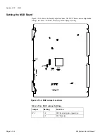

Section 3-9
DEMOD
Page 3-9-2
CM 100Base-T System User’s Manual
Functional Description
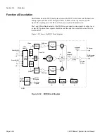
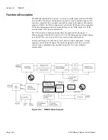
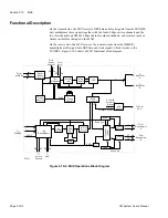
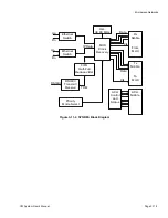
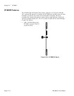
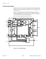
The DEMOD (demodulator), Figure 3-9-2, accepts a QAM signal centered at 70 MHz
from the RXU and removes the modulation to produce I and Q baseband signals. A/D
converters sample the I and Q signals and send the output to the adaptive time domain
equalizer (ATDE). An FPGA configures and controls the ATDE and is also responsible
for the data demapping and decision-directed loops of the ATDE output. The ATDE
provides higher order signal compensation.
The FPGA extracts symbol clock timing from the equalized I and Q signals. A
differential signal from the FPGA drives a VCXO. The demapped I and Q data streams
go to the MUX for conversion back to error-corrected data and overhead.
Analog control loops provide I and Q coarse AGC and slope equalization. A slope
equalizer circuit detects the slope of the baseband signals to assist the coarse AGC
control voltage. Amplitude slope equalization provides first-order multipath
compensation.
Figure 3-9-2. DEMOD Block Diagram
Summary of Contents for CM7
Page 2: ......
Page 4: ...Page iv 5 04 05 CM7 8 100Base T System User s Manual ...
Page 16: ...Glossary Page xvi CM System Users Manual X Y Z ...
Page 24: ...Microwave Networks CM7 8 100Base T System User s Manual Pagexxiv ...
Page 62: ...Chapter 2 Operation Page 2 18 5 02 05 CM 100Base T System User s Manual ...
Page 64: ...Chapter 3 Module Descriptions Page 3 2 CM7 8 100Base T ...
Page 88: ...Section 3 3 Transmitter Unit Page 3 3 6 CM7 8 System User s Manual ...
Page 96: ...Section 3 5 RF Power Supply Unit Page 3 5 4 CM System User s Manual ...
Page 100: ...Section 3 6 SP Power Supply Unit Page 3 6 4 CM System User s Manual ...
Page 106: ...Section 3 7 Alarm and Control Unit Page 3 7 6 11 18 03 CM 100Base T System User s Manual ...
Page 124: ...Section 3 11 SYNDES Page 3 11 6 CM System User s Manual ...
Page 130: ...Section 3 12 SCU Page 3 12 6 11 18 03 CM 100Base T System User s Manual ...
Page 138: ...Section 3 13 OWU Page 3 13 8 CM System User s Manual ...
Page 150: ...Section 3 15 NMU Page 3 15 6 CM System User s Manual ...
Page 192: ...Chapter 5 Verification Page 5 20 CM System User s Manual ...
Page 194: ...Chapter 6 Maintenance Page 6 2 7 23 03 CM 100Base T System User s Manual ...
Page 224: ...Chapter 6 Maintenance Page 6 32 7 23 03 CM 100Base T System User s Manual ...
Page 226: ...Site Engineering Page 2 CM System User s Manual ...
Page 230: ...Appendix A T I Curves Page A 4 CM7 8 100Base T System User s Manual ...
Page 267: ...Microwave Networks CM System User s Manual PageB 37 ...
Page 268: ...Appendix B QuikLink Page B 38 CM System User s Manual ...
Page 282: ...Appendix D Alarm Codes Page D 6 5 02 05 CM 100Base T System User s Manual ...
Page 290: ...Appendix E Setting Frequency Page E 8 CM7 8 System User s Manual ...
Page 312: ...CM7 8 100Base T System User s Manual Page I 4 Microwave Networks ...