


CM System User’s Manual
2/20/04
Page 4-1
Introduction
This chapter provides installation procedures. Topics include:
Introduction . . . . . . . . . . . . . . . . . . . . . . . . . . . . . . 4-1
Preparing the Installation . . . . . . . . . . . . . . . . . . . . 4-1
Installing the Equipment Rack . . . . . . . . . . . . . . . . 4-4
Cabling the Access Panel . . . . . . . . . . . . . . . . . . . . 4-8
Connecting Monitoring Devices . . . . . . . . . . . . . 4-15
Connecting Antennas . . . . . . . . . . . . . . . . . . . . . . 4-21
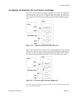
Preparing the Installation
Proper installation planning includes: selecting a site, unpacking the radio, and safely
securing the radio rack or cabinet. Follow the guidelines in this section for trouble-free
radio operation. Installation procedures typically progress in the following stages:
•
Preparing the site
•
Unpacking equipment
•
Installing the rack
•
Cabling signals
•
Installing monitoring equipment
•
Attaching the antennas
Preparing the Site
When selecting a site look for:
1.
Climate-controlled environment with adequate air flow
2.
Ample power
3.
Site grounding that meets either the National Electric Code: USA–Article 250 or the
Canadian Electric Code: Canada–Section 10, and all applicable local standards
4.
Proper floor loading, space, and overhead support
5.
At least three feet clearance in front of the equipment for maintenance
6.
Enough lighting for installation and maintenance
Prepare the floor area and supports for mounting. The equipment rack is a 19-inch floor-
mount type (Figure 4-1). Radio depth is 10.25 inches (260 mm) and the waveguide
branching network adds 4.1875 inches (106 mm). A 15-inch rack footprint allows
sufficient space for the assembled radio.
Prior to securing the rack in an site without rear access, wire power as described in
subsection
Installing the Rack
.
Chapter 4
Equipment Installation
Summary of Contents for CM7
Page 2: ......
Page 4: ...Page iv 5 04 05 CM7 8 100Base T System User s Manual ...
Page 16: ...Glossary Page xvi CM System Users Manual X Y Z ...
Page 24: ...Microwave Networks CM7 8 100Base T System User s Manual Pagexxiv ...
Page 62: ...Chapter 2 Operation Page 2 18 5 02 05 CM 100Base T System User s Manual ...
Page 64: ...Chapter 3 Module Descriptions Page 3 2 CM7 8 100Base T ...
Page 88: ...Section 3 3 Transmitter Unit Page 3 3 6 CM7 8 System User s Manual ...
Page 96: ...Section 3 5 RF Power Supply Unit Page 3 5 4 CM System User s Manual ...
Page 100: ...Section 3 6 SP Power Supply Unit Page 3 6 4 CM System User s Manual ...
Page 106: ...Section 3 7 Alarm and Control Unit Page 3 7 6 11 18 03 CM 100Base T System User s Manual ...
Page 124: ...Section 3 11 SYNDES Page 3 11 6 CM System User s Manual ...
Page 130: ...Section 3 12 SCU Page 3 12 6 11 18 03 CM 100Base T System User s Manual ...
Page 138: ...Section 3 13 OWU Page 3 13 8 CM System User s Manual ...
Page 150: ...Section 3 15 NMU Page 3 15 6 CM System User s Manual ...
Page 192: ...Chapter 5 Verification Page 5 20 CM System User s Manual ...
Page 194: ...Chapter 6 Maintenance Page 6 2 7 23 03 CM 100Base T System User s Manual ...
Page 224: ...Chapter 6 Maintenance Page 6 32 7 23 03 CM 100Base T System User s Manual ...
Page 226: ...Site Engineering Page 2 CM System User s Manual ...
Page 230: ...Appendix A T I Curves Page A 4 CM7 8 100Base T System User s Manual ...
Page 267: ...Microwave Networks CM System User s Manual PageB 37 ...
Page 268: ...Appendix B QuikLink Page B 38 CM System User s Manual ...
Page 282: ...Appendix D Alarm Codes Page D 6 5 02 05 CM 100Base T System User s Manual ...
Page 290: ...Appendix E Setting Frequency Page E 8 CM7 8 System User s Manual ...
Page 312: ...CM7 8 100Base T System User s Manual Page I 4 Microwave Networks ...


