


CM SNMP
Page F-10
6/14/02
CM System User’s Manual
System Operation
Configure the interface and radios, monitor events, query radios, receive responses to
issued commands, or receive unsolicited critical radio data (traps) from a CM radio
with SNMP using an SNMP management application, Telnet, or the command line
interface (CLI).
The management station displays responses or trap data. Trap data updates periodi-
cally. The system connects to Telnet or an SNMP management application through the
Ethernet network, and the CLI connects to the radio local access port.
SNMP Network Manager
Radio management using the CM SNMP private MIB depends largely on the SNMP
management application you use. Refer to the tutorials, help, and documentation of
your specific management software.
Microwave Networks MIB
The CM SNMP MIB contains groups of variables that specify the structure and format
for CM radio management data. The following text explains these variables.
Add and compile the CM SNMP MIB into your SNMP manager. For illustration this
section uses Castlerock SNMPc. See your documentation or administrator for instruc-
tions.
After compiling, perform the following steps to access MIB variables using SNMPc:
1.
Click Start and select Programs.
2.
Open SNMPc (or the name of your commercial SNMP)
3.
Select Startup System from the SNMPc sub-menu
4.
In the login screen, enter your User Name and Password
5.
Click OK
6.
At the Root Subnet Menu, select the subnet that contains the IP address of the
desired radio, and then select the radio.
7.
At the Server Menu, click Tools, and then click MIB Browser.
8.
Open the Private folder.
9.
From the private folder that appears, select Microwave-Networks.
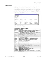
MIB Tables
The figure below shows the major CM SNMP variable categories:
• Performance
monitor radio performance statistics
• Configuration
view and change radio settings
• Fault management
configure and monitor radio alarms
• Trap management
control and monitor traps
• Diagnostics
perform system tests and monitor results
Summary of Contents for CM7
Page 2: ......
Page 4: ...Page iv 5 04 05 CM7 8 100Base T System User s Manual ...
Page 16: ...Glossary Page xvi CM System Users Manual X Y Z ...
Page 24: ...Microwave Networks CM7 8 100Base T System User s Manual Pagexxiv ...
Page 62: ...Chapter 2 Operation Page 2 18 5 02 05 CM 100Base T System User s Manual ...
Page 64: ...Chapter 3 Module Descriptions Page 3 2 CM7 8 100Base T ...
Page 88: ...Section 3 3 Transmitter Unit Page 3 3 6 CM7 8 System User s Manual ...
Page 96: ...Section 3 5 RF Power Supply Unit Page 3 5 4 CM System User s Manual ...
Page 100: ...Section 3 6 SP Power Supply Unit Page 3 6 4 CM System User s Manual ...
Page 106: ...Section 3 7 Alarm and Control Unit Page 3 7 6 11 18 03 CM 100Base T System User s Manual ...
Page 124: ...Section 3 11 SYNDES Page 3 11 6 CM System User s Manual ...
Page 130: ...Section 3 12 SCU Page 3 12 6 11 18 03 CM 100Base T System User s Manual ...
Page 138: ...Section 3 13 OWU Page 3 13 8 CM System User s Manual ...
Page 150: ...Section 3 15 NMU Page 3 15 6 CM System User s Manual ...
Page 192: ...Chapter 5 Verification Page 5 20 CM System User s Manual ...
Page 194: ...Chapter 6 Maintenance Page 6 2 7 23 03 CM 100Base T System User s Manual ...
Page 224: ...Chapter 6 Maintenance Page 6 32 7 23 03 CM 100Base T System User s Manual ...
Page 226: ...Site Engineering Page 2 CM System User s Manual ...
Page 230: ...Appendix A T I Curves Page A 4 CM7 8 100Base T System User s Manual ...
Page 267: ...Microwave Networks CM System User s Manual PageB 37 ...
Page 268: ...Appendix B QuikLink Page B 38 CM System User s Manual ...
Page 282: ...Appendix D Alarm Codes Page D 6 5 02 05 CM 100Base T System User s Manual ...
Page 290: ...Appendix E Setting Frequency Page E 8 CM7 8 System User s Manual ...
Page 312: ...CM7 8 100Base T System User s Manual Page I 4 Microwave Networks ...


