


Microwave Networks
CM System User’s Manual
2/20/04
Page 4-19
Table 4-K lists modem data transfer requirements, and Tables 4-L and 4-M describe
DTE-to-DCE and DTE-to-DTE internal cable connections, respectively.
Note: Consult the modem manual for configuration instruction.
After establishing communication, the QuikLink main screen displays the radio
frequency band, system software part number, and ACU code revision. See Appendix B
for detailed QuikLink information.
If communication between the radio and computer fails, troubleshoot as the previous
verification procedure describes.
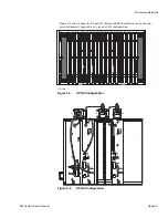
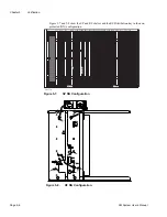
DTE/DCE Wiring
Figure 4-14 shows the DTE and DCE wiring for various connection types.
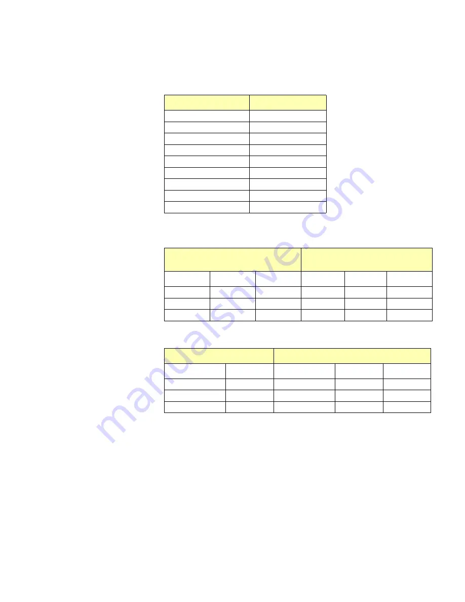
Table 4-K. Modem Communication Requirements
Function
Setting
Baud Rate
9600
Parity
None
Data Bits
8
Stop Bits
1
Terminal Emulation
VT100/220 or ANSI
Flow Control
None
Asynchronous Echo
Off
Results Codes
Disabled
Answer on Ring #
1
Table 4-L. DTE-to-DCE Cable Connections
DTE (CM Radios,
Most computer terminals)
DCE (Most MODEMS)
Function
DB-9
DB-25
Function
DB-9
DB-25
TX Out
3
2
Rx In
3
2
Rx In
2
3
Tx Out
2
3
GND
5
7
GND
5
7
Table 4-M. DTE-to-DTE Cable Connections
DTE
DTE
Function
DB-9
Function
DB-9
DB-25
Tx Out
3
Rx In
3
2
Rx In
2
Tx Out
3
2
GND
5
GND
5
7
Summary of Contents for CM7
Page 2: ......
Page 4: ...Page iv 5 04 05 CM7 8 100Base T System User s Manual ...
Page 16: ...Glossary Page xvi CM System Users Manual X Y Z ...
Page 24: ...Microwave Networks CM7 8 100Base T System User s Manual Pagexxiv ...
Page 62: ...Chapter 2 Operation Page 2 18 5 02 05 CM 100Base T System User s Manual ...
Page 64: ...Chapter 3 Module Descriptions Page 3 2 CM7 8 100Base T ...
Page 88: ...Section 3 3 Transmitter Unit Page 3 3 6 CM7 8 System User s Manual ...
Page 96: ...Section 3 5 RF Power Supply Unit Page 3 5 4 CM System User s Manual ...
Page 100: ...Section 3 6 SP Power Supply Unit Page 3 6 4 CM System User s Manual ...
Page 106: ...Section 3 7 Alarm and Control Unit Page 3 7 6 11 18 03 CM 100Base T System User s Manual ...
Page 124: ...Section 3 11 SYNDES Page 3 11 6 CM System User s Manual ...
Page 130: ...Section 3 12 SCU Page 3 12 6 11 18 03 CM 100Base T System User s Manual ...
Page 138: ...Section 3 13 OWU Page 3 13 8 CM System User s Manual ...
Page 150: ...Section 3 15 NMU Page 3 15 6 CM System User s Manual ...
Page 192: ...Chapter 5 Verification Page 5 20 CM System User s Manual ...
Page 194: ...Chapter 6 Maintenance Page 6 2 7 23 03 CM 100Base T System User s Manual ...
Page 224: ...Chapter 6 Maintenance Page 6 32 7 23 03 CM 100Base T System User s Manual ...
Page 226: ...Site Engineering Page 2 CM System User s Manual ...
Page 230: ...Appendix A T I Curves Page A 4 CM7 8 100Base T System User s Manual ...
Page 267: ...Microwave Networks CM System User s Manual PageB 37 ...
Page 268: ...Appendix B QuikLink Page B 38 CM System User s Manual ...
Page 282: ...Appendix D Alarm Codes Page D 6 5 02 05 CM 100Base T System User s Manual ...
Page 290: ...Appendix E Setting Frequency Page E 8 CM7 8 System User s Manual ...
Page 312: ...CM7 8 100Base T System User s Manual Page I 4 Microwave Networks ...