Microwave Networks
CM System User’s Manual
2/20/04
Page 4-13
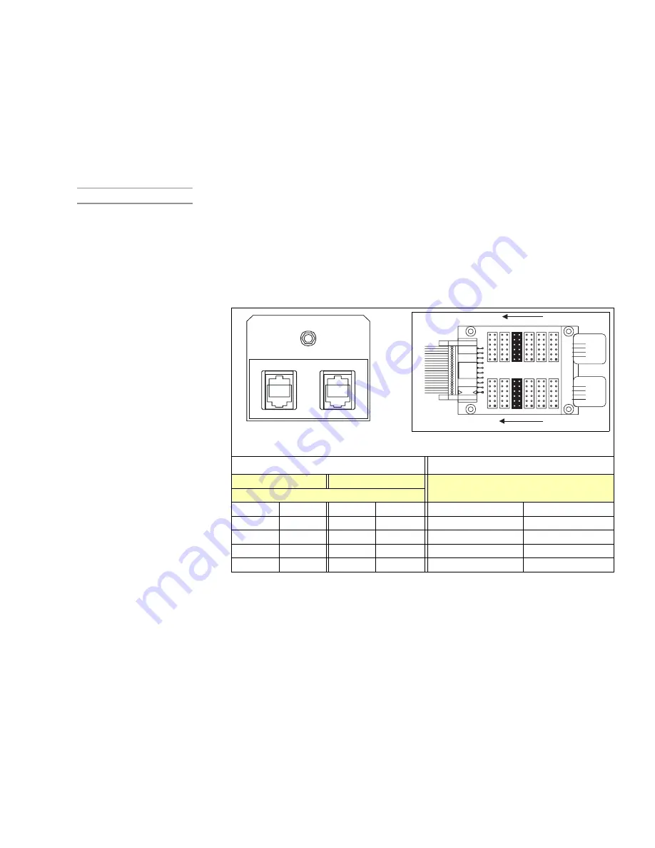
The network port (Table 4-H) connects network management data to co-located radios
and the Telescan network management system. The high-capacity access panel accepts a
uni- or omni-directional (RS-422) connection. The omni-directional connection involves
setting the NMU to a 4-port bridge element (Figure 3-1-1). Jumpers on the Network
Bridge Interface (Table 4-I) behind the front panel set the network connector as uni- (E4
and E10 in) or omni-directional (E5 and E12 in) while NMU jumpers set the bridge
configuration.
SNMP Note
See Appendix G to install and configure an SNMP Network.
Table 4-I lists the network connection pinning. Tx refers to signals out of the radio, Rx to
signals to the radio. Master/Slave and West/East labels refer to network (NMS)
configurations discussed above. To bridge network management data use connections as
Figure 4-10 illustrates.
Table 4-I. Network Port Connections
3-Port Bridge (unidirectional) Interface
4-Port Bridge (omni-directional)
Master Radio
Slave Radio
East and West
(on separate terminals)
(on one terminal)
Pin
Signal
Pin
Signal
Pin
Signal
2
TX+
2
RX+
2
TX-
3
TX-
3
RX-
3
TX+
4
RX+
4
TX+
4
RX+
5
RX-
5
TX-
5
RX-
Pin 1 is at the left of the jacks. Tx/RX signal direction is from the radio view. Tx means sig-
nals from the radio; Rx means signals to the radio.
NE T WO RK
EA ST
W EST
2
1
MNI IN
1
2
MNI OU
T
1
2
2
1
ACU/NMU MS
ACU/NMU SL
1
1
2
2
1
2
FU
T
U
R
E
ACU68K
12
12
1
2
MNI IN
11
E1
11
1
2
MNI OU
T
11
12
E2
1
2
2
ACU/NMU MS
1
11
12
E3
12
E4
11
ACU/NMU SL
11
12
11
12
12
11
E7
E1
E8
E9
E10
1
11
2
2
1
FU
T
U
R
E
12
11
12
E6
E5
ACU68K
11
12
12
11
J1
19
20
E12
E6
E11
cabling
ports
Front Panel Network Port
Network Interface Card behind panel
Summary of Contents for CM7
Page 2: ......
Page 4: ...Page iv 5 04 05 CM7 8 100Base T System User s Manual ...
Page 16: ...Glossary Page xvi CM System Users Manual X Y Z ...
Page 24: ...Microwave Networks CM7 8 100Base T System User s Manual Pagexxiv ...
Page 62: ...Chapter 2 Operation Page 2 18 5 02 05 CM 100Base T System User s Manual ...
Page 64: ...Chapter 3 Module Descriptions Page 3 2 CM7 8 100Base T ...
Page 88: ...Section 3 3 Transmitter Unit Page 3 3 6 CM7 8 System User s Manual ...
Page 96: ...Section 3 5 RF Power Supply Unit Page 3 5 4 CM System User s Manual ...
Page 100: ...Section 3 6 SP Power Supply Unit Page 3 6 4 CM System User s Manual ...
Page 106: ...Section 3 7 Alarm and Control Unit Page 3 7 6 11 18 03 CM 100Base T System User s Manual ...
Page 124: ...Section 3 11 SYNDES Page 3 11 6 CM System User s Manual ...
Page 130: ...Section 3 12 SCU Page 3 12 6 11 18 03 CM 100Base T System User s Manual ...
Page 138: ...Section 3 13 OWU Page 3 13 8 CM System User s Manual ...
Page 150: ...Section 3 15 NMU Page 3 15 6 CM System User s Manual ...
Page 192: ...Chapter 5 Verification Page 5 20 CM System User s Manual ...
Page 194: ...Chapter 6 Maintenance Page 6 2 7 23 03 CM 100Base T System User s Manual ...
Page 224: ...Chapter 6 Maintenance Page 6 32 7 23 03 CM 100Base T System User s Manual ...
Page 226: ...Site Engineering Page 2 CM System User s Manual ...
Page 230: ...Appendix A T I Curves Page A 4 CM7 8 100Base T System User s Manual ...
Page 267: ...Microwave Networks CM System User s Manual PageB 37 ...
Page 268: ...Appendix B QuikLink Page B 38 CM System User s Manual ...
Page 282: ...Appendix D Alarm Codes Page D 6 5 02 05 CM 100Base T System User s Manual ...
Page 290: ...Appendix E Setting Frequency Page E 8 CM7 8 System User s Manual ...
Page 312: ...CM7 8 100Base T System User s Manual Page I 4 Microwave Networks ...