


Appendix B
QuikLink
Page B-20
CM System Users Manual
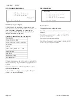
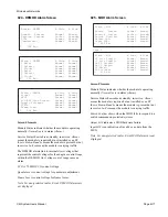
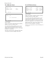
029 - RXU Alarm Screen
Screen Elements
Module Status
indicates whether the receiver is operating
normally (
Normal
) or is in alarm (
Alarm
.)
Service Status
shows absent, standby, in-service.
Absent
means the module not installed or an SP fuse is blown.
Standby
means the module is not in service.
In-Svc
means the
module is carrying traffic.
LO
indicates the operational status of the synthesized local
oscillator in the RXU. An alarm occurs if either:
1. There is insufficient drive level to the mixer in the conversion
section of the RXU.
2. The microwave oscillator is not phase-locked to the internal
reference.
AGC
indicates the operational status of the automatic gain
control circuitry of the receiver IF amplifier.
Preamplifier
shows the condition of the preamp (if used.)
Regulated Voltage
shows condition of the low noise amplifier
section of the RXU.
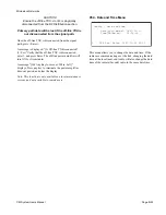
Note: For non-protected radios, B side RXU alarms are not
displayed.
L 029 Esc
Alarm - RXU A Side B Side
Module Status: Normal Normal
Service Status: In-Svc Standby
LO: Normal Normal
AGC: Normal Normal
Preamplifier: Normal Normal
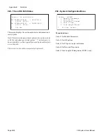
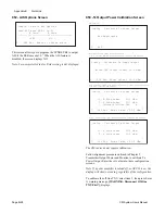
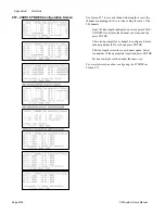
Protected 2, 6, 10, & 11 GHz Radios
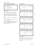
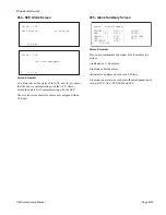
Protected 7/8 GHz Radios
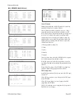
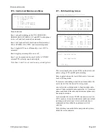
Protected CM Radios
Alarm - RXU A Side B Side
Module Status: Normal Normal
Service Status: In-Svc Standby
LO: Normal Normal
AGC: Normal Normal
L 029 Esc o
Alarm - RXU A Side B Side
Module Status: Normal Normal
Service Status: In-Svc Standby
LO: Normal Normal
AGC: Normal Normal
Regulated Voltage: Normal Normal
L 029 Esc
Summary of Contents for CM7
Page 2: ......
Page 4: ...Page iv 5 04 05 CM7 8 100Base T System User s Manual ...
Page 16: ...Glossary Page xvi CM System Users Manual X Y Z ...
Page 24: ...Microwave Networks CM7 8 100Base T System User s Manual Pagexxiv ...
Page 62: ...Chapter 2 Operation Page 2 18 5 02 05 CM 100Base T System User s Manual ...
Page 64: ...Chapter 3 Module Descriptions Page 3 2 CM7 8 100Base T ...
Page 88: ...Section 3 3 Transmitter Unit Page 3 3 6 CM7 8 System User s Manual ...
Page 96: ...Section 3 5 RF Power Supply Unit Page 3 5 4 CM System User s Manual ...
Page 100: ...Section 3 6 SP Power Supply Unit Page 3 6 4 CM System User s Manual ...
Page 106: ...Section 3 7 Alarm and Control Unit Page 3 7 6 11 18 03 CM 100Base T System User s Manual ...
Page 124: ...Section 3 11 SYNDES Page 3 11 6 CM System User s Manual ...
Page 130: ...Section 3 12 SCU Page 3 12 6 11 18 03 CM 100Base T System User s Manual ...
Page 138: ...Section 3 13 OWU Page 3 13 8 CM System User s Manual ...
Page 150: ...Section 3 15 NMU Page 3 15 6 CM System User s Manual ...
Page 192: ...Chapter 5 Verification Page 5 20 CM System User s Manual ...
Page 194: ...Chapter 6 Maintenance Page 6 2 7 23 03 CM 100Base T System User s Manual ...
Page 224: ...Chapter 6 Maintenance Page 6 32 7 23 03 CM 100Base T System User s Manual ...
Page 226: ...Site Engineering Page 2 CM System User s Manual ...
Page 230: ...Appendix A T I Curves Page A 4 CM7 8 100Base T System User s Manual ...
Page 267: ...Microwave Networks CM System User s Manual PageB 37 ...
Page 268: ...Appendix B QuikLink Page B 38 CM System User s Manual ...
Page 282: ...Appendix D Alarm Codes Page D 6 5 02 05 CM 100Base T System User s Manual ...
Page 290: ...Appendix E Setting Frequency Page E 8 CM7 8 System User s Manual ...
Page 312: ...CM7 8 100Base T System User s Manual Page I 4 Microwave Networks ...


