


Chapter 4
Installation
Page 4-16
2/20/04
CM System User’s Manual
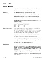
Connecting Local Access
The computer or terminal serial communications (COM) port is either a Sub-D 9-pin
connector, or Sub-DB 25-pin connector. The local access port on the radio is a female
Sub-D 9-pin connector that carries three RS-232 compatible signals (Table 4-J). Connect
the terminal using the following steps.
1.
Locate the serial communications port.
2.
Create the appropriate cable for the specific application using the wiring diagrams in
Figures 4-11 and 4-12.
3.
Set your computer/terminal serial port to DTE (data terminal equipment), 9600 bps, 8-
bit-long word, 1-stop bit and no parity.
Note:
DO NOT set XON/XOFF, hardware flow control or hardware modem control signals.
After establishing communications, the terminal/computer displays the QuikLink main
screen that shows the radio frequency band, system software part number, and ACU code
revision level.
See Appendix B for a description of QuikLink and operating instructions.
Table 4-J. Local Access Port
Pin
Signal
1
2
INPUT (RX)
3
OUTPUT (TX)
4
5
GND
6
TTL Input 7
7
8
GND
9
For IBM-compatible computers, that have a DB9 connector, Pins 7 and 8, and
4 and 6, should be connected together at DB9 on the computer
L O CA L A CC E SS
DT E
DC E
1
6
5
9
Summary of Contents for CM7
Page 2: ......
Page 4: ...Page iv 5 04 05 CM7 8 100Base T System User s Manual ...
Page 16: ...Glossary Page xvi CM System Users Manual X Y Z ...
Page 24: ...Microwave Networks CM7 8 100Base T System User s Manual Pagexxiv ...
Page 62: ...Chapter 2 Operation Page 2 18 5 02 05 CM 100Base T System User s Manual ...
Page 64: ...Chapter 3 Module Descriptions Page 3 2 CM7 8 100Base T ...
Page 88: ...Section 3 3 Transmitter Unit Page 3 3 6 CM7 8 System User s Manual ...
Page 96: ...Section 3 5 RF Power Supply Unit Page 3 5 4 CM System User s Manual ...
Page 100: ...Section 3 6 SP Power Supply Unit Page 3 6 4 CM System User s Manual ...
Page 106: ...Section 3 7 Alarm and Control Unit Page 3 7 6 11 18 03 CM 100Base T System User s Manual ...
Page 124: ...Section 3 11 SYNDES Page 3 11 6 CM System User s Manual ...
Page 130: ...Section 3 12 SCU Page 3 12 6 11 18 03 CM 100Base T System User s Manual ...
Page 138: ...Section 3 13 OWU Page 3 13 8 CM System User s Manual ...
Page 150: ...Section 3 15 NMU Page 3 15 6 CM System User s Manual ...
Page 192: ...Chapter 5 Verification Page 5 20 CM System User s Manual ...
Page 194: ...Chapter 6 Maintenance Page 6 2 7 23 03 CM 100Base T System User s Manual ...
Page 224: ...Chapter 6 Maintenance Page 6 32 7 23 03 CM 100Base T System User s Manual ...
Page 226: ...Site Engineering Page 2 CM System User s Manual ...
Page 230: ...Appendix A T I Curves Page A 4 CM7 8 100Base T System User s Manual ...
Page 267: ...Microwave Networks CM System User s Manual PageB 37 ...
Page 268: ...Appendix B QuikLink Page B 38 CM System User s Manual ...
Page 282: ...Appendix D Alarm Codes Page D 6 5 02 05 CM 100Base T System User s Manual ...
Page 290: ...Appendix E Setting Frequency Page E 8 CM7 8 System User s Manual ...
Page 312: ...CM7 8 100Base T System User s Manual Page I 4 Microwave Networks ...


