


CM System User’s Manual
6/14/02
Page F-9
Microwave Networks
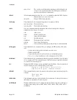
server as Figure F-6 shows.
• Set RIP to let radios exchange IP information so that all network devices deter-
mine how to reach any other device in the network. You can also manually edit
routing information for smaller networks.
• Set the first radio connected to an existing network as the “intermediate gate-
way" (Figure F-6). The intermediate gateway serves as an entrance to the sub-
net of radios. When you reach the 15-radio limit of RIP, you can start another
radio subnet by using its first radio as its intermediate gateway.
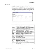
Figure F-5 shows an example of the
setup_ppp
entries. The gateway IP
address is 172.17.0.0 for this subnet of radios with addresses from 172.17.1.1
to 172.17.1.30 (each radio using two addresses).
Figure F-5. Example of
setup-ppp
Entries
Use the SHUTDOWN command to ensure flash memory gets
updated before reboot or removing power from the board.
Company
LAN
Gateway
Ethernet
Intermediate
Gateway
RADIO
SUBNET
IF
1
IF
2
IF
2
CLIENT
SERVER
Telnet of SNMP
application
Figure F-6. Example of Radio Network Connections
Summary of Contents for CM7
Page 2: ......
Page 4: ...Page iv 5 04 05 CM7 8 100Base T System User s Manual ...
Page 16: ...Glossary Page xvi CM System Users Manual X Y Z ...
Page 24: ...Microwave Networks CM7 8 100Base T System User s Manual Pagexxiv ...
Page 62: ...Chapter 2 Operation Page 2 18 5 02 05 CM 100Base T System User s Manual ...
Page 64: ...Chapter 3 Module Descriptions Page 3 2 CM7 8 100Base T ...
Page 88: ...Section 3 3 Transmitter Unit Page 3 3 6 CM7 8 System User s Manual ...
Page 96: ...Section 3 5 RF Power Supply Unit Page 3 5 4 CM System User s Manual ...
Page 100: ...Section 3 6 SP Power Supply Unit Page 3 6 4 CM System User s Manual ...
Page 106: ...Section 3 7 Alarm and Control Unit Page 3 7 6 11 18 03 CM 100Base T System User s Manual ...
Page 124: ...Section 3 11 SYNDES Page 3 11 6 CM System User s Manual ...
Page 130: ...Section 3 12 SCU Page 3 12 6 11 18 03 CM 100Base T System User s Manual ...
Page 138: ...Section 3 13 OWU Page 3 13 8 CM System User s Manual ...
Page 150: ...Section 3 15 NMU Page 3 15 6 CM System User s Manual ...
Page 192: ...Chapter 5 Verification Page 5 20 CM System User s Manual ...
Page 194: ...Chapter 6 Maintenance Page 6 2 7 23 03 CM 100Base T System User s Manual ...
Page 224: ...Chapter 6 Maintenance Page 6 32 7 23 03 CM 100Base T System User s Manual ...
Page 226: ...Site Engineering Page 2 CM System User s Manual ...
Page 230: ...Appendix A T I Curves Page A 4 CM7 8 100Base T System User s Manual ...
Page 267: ...Microwave Networks CM System User s Manual PageB 37 ...
Page 268: ...Appendix B QuikLink Page B 38 CM System User s Manual ...
Page 282: ...Appendix D Alarm Codes Page D 6 5 02 05 CM 100Base T System User s Manual ...
Page 290: ...Appendix E Setting Frequency Page E 8 CM7 8 System User s Manual ...
Page 312: ...CM7 8 100Base T System User s Manual Page I 4 Microwave Networks ...


