


Section 3-11
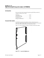
SYNDES
Page 3-11-2
CM System User’s Manual
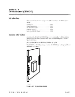
Functional Description
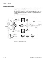
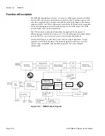
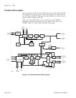
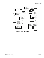
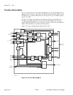
The SYNDES plugs into the signal processing shelf. It takes customer signal traffic and
formats it into radio transportable data. SYNDES functions to complete the signal
preparation and conversion include:
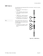
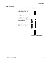
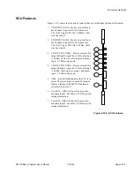
•
Sensing 10/100Base-T signal
•
Sensing full/half-duplex mode
•
Synchronizing signal flow
•
Encoding and decoding the data stream
•
Controlling line status—turns lines on and off
•
Monitoring the signal path and generating alarm indication (blue)
signal
•
Initiating the learning bridge-learns which devices are on each of its
interfaces.
•
Setting the virtual LAN (VLAN) mode—port 1 in to port 1 out, port
2 in to port 2 out
Transmit
For Ethernet input, the interface senses if the connected network is 100- or 10-BaseT and
half or full duplex. The SYNDES recovers Ethernet data and clock from the input signal,
and determines, based on the Ethernet address, whether the packet needs to cross the link.
Data for transmission is then sent to the MUX interface on a packet-by-packet basis. Data
stream bandwidth for each Ethernet port is either 155-, 120-, or 110-bps and depends on
whether the data stream includes a DS3 or E3 channel. Priority settings, Chapter 4,
Paragraph 4.0, commit bandwidth to each port.
The SYNDES recovers data and clock from the DS3 or E3 input data stream and sends
this directly to the MUX interface at 44.736 MHz (DS3) or 34.368 MHz (E3).
In all cases, data travels as frames to the MUX interface at 155.52 Mbps via a 4-bit
interface. Data frames include bits reserved for DS3 or E3 data and bits reserved for
Ethernet packet data. The frame structure varies as to whether DS3, E3, or wayside data
is combined with Ethernet data.
Receive
The MUX sends 4-bit nibbles of data to the SYNDES using a 47-MHz clock and a gap
signal, so that the average data rate is 155.52 Mbps. The SYNDES finds the frame
boundaries and separates the Ethernet packet data from DS3/E3 data.
For each Ethernet packet, the SYNDES determines whether the packet belongs on LAN
A or B and sends the data to the appropriate switch. Switches decide which interface to
send the packet out on (using the Ethernet address) and encodes and transmits the packet.
DS3/E3 data stream goes to a line encoder chip through a FIFO buffer. The
desynchronizer monitors the FIFO to adjust the rate at which data goes to the line
encoder; nominally 44.736 MHz (DS3) or 34.368 MHz (E3). The line encoder then
encodes the signal and transmits the data.
Summary of Contents for CM7
Page 2: ......
Page 4: ...Page iv 5 04 05 CM7 8 100Base T System User s Manual ...
Page 16: ...Glossary Page xvi CM System Users Manual X Y Z ...
Page 24: ...Microwave Networks CM7 8 100Base T System User s Manual Pagexxiv ...
Page 62: ...Chapter 2 Operation Page 2 18 5 02 05 CM 100Base T System User s Manual ...
Page 64: ...Chapter 3 Module Descriptions Page 3 2 CM7 8 100Base T ...
Page 88: ...Section 3 3 Transmitter Unit Page 3 3 6 CM7 8 System User s Manual ...
Page 96: ...Section 3 5 RF Power Supply Unit Page 3 5 4 CM System User s Manual ...
Page 100: ...Section 3 6 SP Power Supply Unit Page 3 6 4 CM System User s Manual ...
Page 106: ...Section 3 7 Alarm and Control Unit Page 3 7 6 11 18 03 CM 100Base T System User s Manual ...
Page 124: ...Section 3 11 SYNDES Page 3 11 6 CM System User s Manual ...
Page 130: ...Section 3 12 SCU Page 3 12 6 11 18 03 CM 100Base T System User s Manual ...
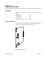
Page 138: ...Section 3 13 OWU Page 3 13 8 CM System User s Manual ...
Page 150: ...Section 3 15 NMU Page 3 15 6 CM System User s Manual ...
Page 192: ...Chapter 5 Verification Page 5 20 CM System User s Manual ...
Page 194: ...Chapter 6 Maintenance Page 6 2 7 23 03 CM 100Base T System User s Manual ...
Page 224: ...Chapter 6 Maintenance Page 6 32 7 23 03 CM 100Base T System User s Manual ...
Page 226: ...Site Engineering Page 2 CM System User s Manual ...
Page 230: ...Appendix A T I Curves Page A 4 CM7 8 100Base T System User s Manual ...
Page 267: ...Microwave Networks CM System User s Manual PageB 37 ...
Page 268: ...Appendix B QuikLink Page B 38 CM System User s Manual ...
Page 282: ...Appendix D Alarm Codes Page D 6 5 02 05 CM 100Base T System User s Manual ...
Page 290: ...Appendix E Setting Frequency Page E 8 CM7 8 System User s Manual ...
Page 312: ...CM7 8 100Base T System User s Manual Page I 4 Microwave Networks ...


