


Appendix B
QuikLink
Page B-26
CM System Users Manual
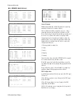
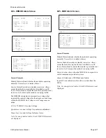
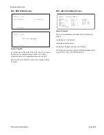
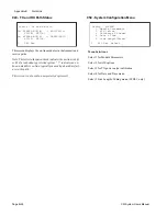
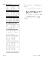
040 - TX and RX Path Status
This screen displays the on-line modules in the transmit and
receive paths.
Note: The letter in the parenthesis indicates the on-line side (A
or B) of a redundancy protected system. “?” indicates an un-
known module is on-line; typically caused by a hardware fail-
ure in the path.
This screen is not used in non-protected systems.G
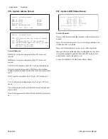
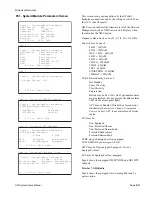
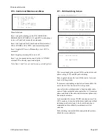
050 - System Configuration Menu
Menu Selections
Select 1 for Module Parameters.
Select 2 for AIS options.
Select 3 for TX power output calibration.
Select 4 for Date and Time menu.
Select 5 Line Lengths/Coding menu (28 DS1, only.)
L 040 Esc
Status - Tx and Rx Path
Tx: SYNDES-MUX(B) -> MOD/TXU(A)
SCU(B) WTU(A)
Rx: SYNDES-MUX(A) <- DEMOD/RXU(?)
SCU(A) WTU(B)
L 050 Esc Select _
Config - SYSTEM
1. Module Parameters
2. AIS Option
3. Calibrate Tx Power
4. Date & Time
5. Line Length/Format
Summary of Contents for CM7
Page 2: ......
Page 4: ...Page iv 5 04 05 CM7 8 100Base T System User s Manual ...
Page 16: ...Glossary Page xvi CM System Users Manual X Y Z ...
Page 24: ...Microwave Networks CM7 8 100Base T System User s Manual Pagexxiv ...
Page 62: ...Chapter 2 Operation Page 2 18 5 02 05 CM 100Base T System User s Manual ...
Page 64: ...Chapter 3 Module Descriptions Page 3 2 CM7 8 100Base T ...
Page 88: ...Section 3 3 Transmitter Unit Page 3 3 6 CM7 8 System User s Manual ...
Page 96: ...Section 3 5 RF Power Supply Unit Page 3 5 4 CM System User s Manual ...
Page 100: ...Section 3 6 SP Power Supply Unit Page 3 6 4 CM System User s Manual ...
Page 106: ...Section 3 7 Alarm and Control Unit Page 3 7 6 11 18 03 CM 100Base T System User s Manual ...
Page 124: ...Section 3 11 SYNDES Page 3 11 6 CM System User s Manual ...
Page 130: ...Section 3 12 SCU Page 3 12 6 11 18 03 CM 100Base T System User s Manual ...
Page 138: ...Section 3 13 OWU Page 3 13 8 CM System User s Manual ...
Page 150: ...Section 3 15 NMU Page 3 15 6 CM System User s Manual ...
Page 192: ...Chapter 5 Verification Page 5 20 CM System User s Manual ...
Page 194: ...Chapter 6 Maintenance Page 6 2 7 23 03 CM 100Base T System User s Manual ...
Page 224: ...Chapter 6 Maintenance Page 6 32 7 23 03 CM 100Base T System User s Manual ...
Page 226: ...Site Engineering Page 2 CM System User s Manual ...
Page 230: ...Appendix A T I Curves Page A 4 CM7 8 100Base T System User s Manual ...
Page 267: ...Microwave Networks CM System User s Manual PageB 37 ...
Page 268: ...Appendix B QuikLink Page B 38 CM System User s Manual ...
Page 282: ...Appendix D Alarm Codes Page D 6 5 02 05 CM 100Base T System User s Manual ...
Page 290: ...Appendix E Setting Frequency Page E 8 CM7 8 System User s Manual ...
Page 312: ...CM7 8 100Base T System User s Manual Page I 4 Microwave Networks ...