Using Baker DX Non-Test Functions
megger.com
43
Touching the
User Settings
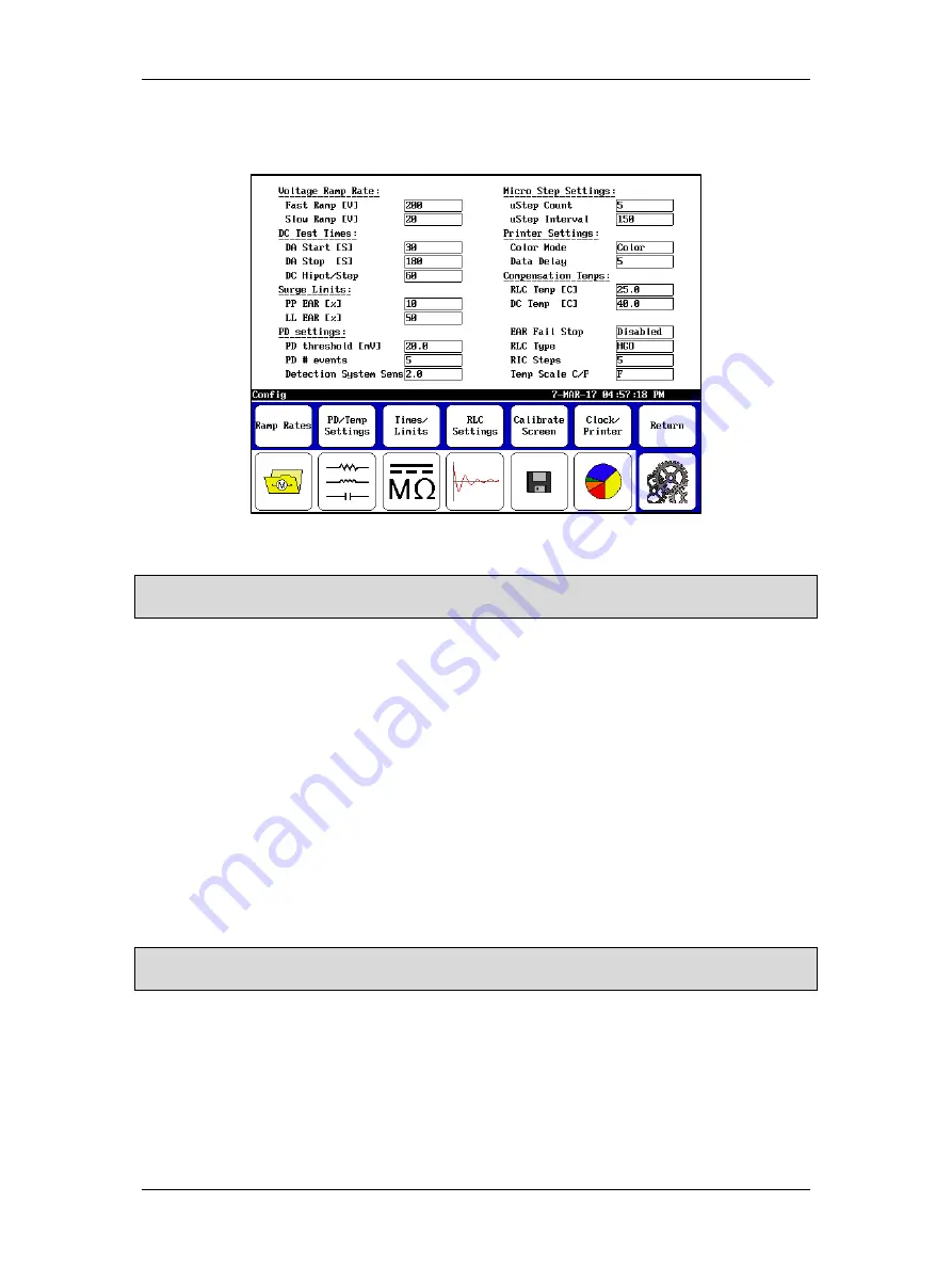
icon (with maintenance mode enabled) opens the screen shown
below. Using this screen, you can change several of the parameters used during testing.
Figure 46. User Settings screen.
NOTICE: To avoid creating problems with the tester, Micro Step Settings should not be changed without first
consulting Megger support. These fields are usually locked out.
Use this screen to adjust the
Voltage Ramp Rate
,
Temperature Scale
(Celsius vs. Fahrenheit),
DC Test Times
(in seconds), and
Surge Limits
(Pulse-to-Pulse EAR and Line-to-Line EAR
maximum limits in percent).
The
RIC Steps
are the degree step increments used when plotting the RIC (rotor influence check)
tests. Increments are 2, 5, 10, and 15 degrees. Smaller step sizes equal higher resolution. Use a
value that gives you enough data points. Having too few data points can make it difficult to get
a good representation of the waveform.
The
Compensation Temperatures
(in Celsius) set here are the “compensate to” temperatures
(standards) used in testing. The “compensate from” temperatures are current winding
temperatures defined during the actual RLC or DC test procedures.
The
EAR Fail Stop
field is used to determine whether tests should stop if they exceed the EAR
limits defined under
Surge Limits
. When this is disabled, the test will not stop but a “warning”
appears in a red box within the test display area when a limit threshold is crossed. If this is
enabled, the test will stop when the threshold is crossed.
NOTICE: If you are concerned about potential damage to the unit under test—such as coil arcing—when EAR
limits are exceeded, you should consider enabling EAR Fail Stop.
The
RLC Type
field identifies the connection settings you will be using (HGG: Hot Ground
Ground, or HGO: Hot Ground Open).
Use the
Printer Settings
section to define your printer color mode and data delay settings. All
successfully tested printers had the following DX printer settings:
Color Mode:
Color
Data Delay:
5
Summary of Contents for Baker DX
Page 1: ......
Page 2: ......
Page 10: ...Table of Contents viii Baker DX 71 030 User Guide EN V10 www megger com...
Page 28: ...Baker DX Instrument Overview 18 Baker DX 71 030 User Guide EN V10 www megger com...
Page 38: ...Baker DX User Interface Overview 28 Baker DX 71 030 User Guide EN V10 www megger com...
Page 58: ...Setting up the Baker DX Tester 48 Baker DX 71 030 User Guide EN V10 www megger com...
Page 149: ...megger com 139 RIC Templates Figure 141 RIC template 1...
Page 150: ...RIC templates 140 Baker DX 71 030 User Guide EN V10 www megger com Figure 142 RIC template 2...
Page 155: ...Index megger com 145...
Page 156: ...megger com 146...


