


LUTRON
Control Unit
Installation and Operation Guide
®
Please Read
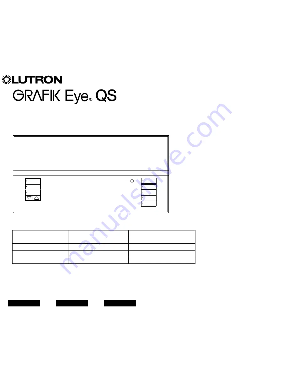
The GRAFIK Eye
®
QS control unit allows for
control of both lights and shades, without
interfaces, using a single control unit.
Features include pushbutton scene recall,
info screen that displays energy savings and
status, IR receiver, astronomic timeclock,
contact closure input, and engravable
backlit buttons that are easy to find and
operate.
Model Numbers: QSGRJ-3P, QSGRJ-4P, QSGRJ-6P
QSGR-3P, QSGR-4P, QSGR-6P
120 V
~
50/60 Hz
220 - 240 V
~
50/60 Hz
Unit Capacity (watts)
2000 W
3000 W
MLV
2000 VA / 1600 W
3000 VA / 2400 W
Zone Capacity (watts)
25 – 800 W
40 – 1200 W
MLV
25 – 800 VA / 25 – 600 W
40 – 1200 VA / 40 – 960 W
See page 7 for IEC PELV/NEC
®
Class 2 ratings.
For California residents only:
The batteries in these devices contain
Perchlorate Material – special handling may apply.
For more information visit
www.dtsc.ca.gov/hazardouswaste/perchlorate
English
Español
Français


