


K-CONFIG – Contents
v
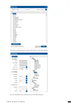
Figure 233: Timer Events – the Timer Trigger Name Window (Inactivity)
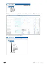
Figure 234: Timer Events – the Timer Trigger in the Triggers List (System Inactivity)
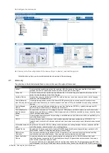
Figure 235: Timer Events – Timer Trigger Action List
Figure 236: Timer Events – Button 1 Action List
Figure 237: Timer Events – Add the Stop Timer Action
Figure 238: Timer Events – Move the Stop Timer Action
Figure 239: Timer Events – Add the Start Timer Action
Figure 240: Timer Events – Button 1 Action List with Timer Triggers
Figure 241: Query Events – The Query Events Window
Figure 242: Query Events – Select the Query
Figure 243: Query Events – The Query Results
Figure 244: Query Events – Select the Query Results
Figure 245: Query Events – The Power-On Trigger
Figure 246: Query Events – Creating Several Query Triggers
Figure 247: Sub Routines – Create a new Action Group Trigger
Figure 248: Sub Routines – Set the Sub Routine Trigger Name
Figure 249: Sub Routines – Set the Action Group Trigger Name
Figure 250: Sub Routines – Selecting the Sub Routine Action Group Trigger in the Action Editor
Figure 251: Sub Routines – Sub Routine Trigger is added to an Event Trigger
Figure 252: The Action Editor – Available Action Types
Figure 253: Selecting the Port Command Action Type
Figure 254: Selecting the Command
Figure 255: The New Command in the Action List
Figure 256: The Action List for the All On Trigger
Figure 257: The All On Trigger (after adding commands to the action list)
Figure 258: The Table Port Command
Figure 259: The Table Port Command – Setting a specific Volume Level
Figure 260: The Table Port Command – Added to the Action List
Figure 261: Selecting the Port Switch Action Type
Figure 262: Port Switch Action Type added to the Action List
Figure 263: Panels Status Action Editor
Figure 264: Panels Status Action List
Figure 265: Panels Status Action – as Appears in the Action Editor
Figure 266: Panels Status – Selecting a Button
Figure 267: Panel Status – Panel Lock
Figure 268: Panel Status – Panel Lock or Unlock State
Figure 269: Switcher Command – Select an Input
Figure 270: Power Amplifier – Select an input
Figure 271: Timer Start/Stop – Select a Timer Trigger
Figure 272: Delay – Set the Delay Time
Figure 273: Query Start/Stop – Selecting the Query Trigger
Figure 274: Sub Routines – Select a Sub Routine
Figure 275: Site Control Message – Select the Query Event
Figure 276: Connection Method Window
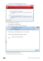
Figure 278: Configuration Mismatch Warning
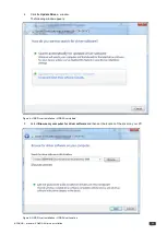
Figure 279: Local Area Connection Properties Window
Figure 280: Internet Protocol Version 4 Properties Window
Figure 281: Internet Protocol Version 6 Properties Window
Figure 282: Internet Protocol Properties Window
Figure 283: KNET ID – A Controlled Room Setting Example
Figure 284: KNET ID – Connect the Device Directly to PC
Figure 285: KNET ID – The K-NET ID Connect Window
Figure 286: KNET ID – Setting K-NET ID
Figure 287: KNET ID –K-NET ID assigned
Figure 288: Firmware Update Window
Figure 289: Load Firmware Upgrade Window
Figure 290: Firmware Upgrade Warning
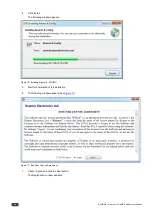
Figure 291: Firmware Upgrade Process
Figure 292: Firmware Upgrade Successful
Figure 293: Firmware Upgrade Process Complete
Figure 294: General Device Settings
Figure 295: Selecting an auxiliary device
Figure 296: Auxiliary Device Settings
Figure 297: The Dim Light Power Feature
Figure 300: Date and Time Settings
Figure 301: Discovering a Room Controller Device
Figure 302: Loading a Configuration
Figure 303: Write Configuration warning
Figure 304: Write Configuration warning (without the KPR Project)
Figure 305: Writing Configuration and Device Resetting Process
Figure 306: Writing Configuration Complete
Figure 307: Writing Project Complete
Figure 309: Read Configuration from Device – New Project Message
Figure 310: Read Configuration from Device – Reading Process


