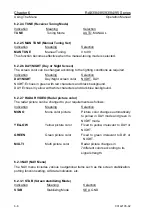
Chapter 6 RA83/84/85/93/94/95 Series
Using The Menu
Operation Manual
the split of the transmitting energy generated by the magnetron (transmitting tube).
6.3.2.7
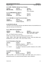
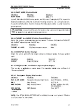
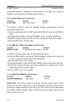
TARGET LEVEL (Target Detection Level)
Indication
Meaning
Selection
TARGET LEVEL
Target Detection Level
1 to 8
This function is used to set the signal level to be supplied to the ATA system. Use the
following procedure to select a signal level.
(1) Highlight the TARGET LEVEL. The signal level increases in ascending order.
(2) Press the ENT key to set the ready to select status.
Press the Joystick up or down to select an appropriate level and press the ENT key to
set up the level.
6.4 SYSTEM MENU
The SYSTEM menu has I/O SETUP, SYS SETUP, and BITE functions. Details of each
function is as follows:
6.4.1 I/O SETUP
This function is used to select the data source supplied from a speed sensor and a
bearing sensor.
NOTE:
This menu is protected from ordinary operations. To use this function, turn off the
radar first. Press and hold the MODE key and turn the radar on again. When the standby
condition is established, turn the radar on to enter the following menu functions.
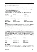
6.4.1.1
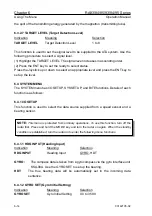
HDG INPUT (Heading Input)
Indication
Meaning Selection
HDG INPUT
Heading Input
GYRO, HDT
GYRO:
The compass data is taken from a gyrocompass via the gyro interface unit
KSA-08A. Use the GYRO SET to set up the bearing.
HDT:
The true bearing data will be automatically set in the incoming data
sentence.
6.4.1.2
GYRO SET (Gyro Initial Setting)
Indication
Meaning Selection
GYRO SET
Gyro Initial Setting
0.0 to 359.9
6-14
93142105-02


