Chapter 4 RA83/84/85/93/94/95 Series
Installation OperationManual
4.8.2 Remote Display operation
A Processor Unit type RP100A can be used as a remote display. To use the display in
this configuration, use the following procedure.
4.8.2.1 Connecting the Remote Display
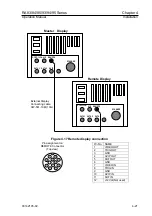
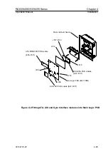
Connect the Master display (RP100A) and a Remote display (RP100A) with the
connecting cable CW-561 (10m) as shown in Figure 4.16.
4.8.2.2 Required set up
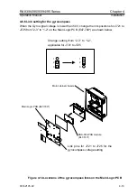
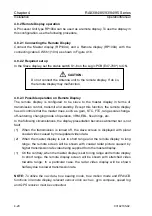
In the Slave display, set the status switch S1-6 on the Logic PCB (E47-700*) to ON.
CAUTION:
Do not connect the Antenna unit to the remote display. If do so,
the remote display may malfunction.
4.8.2.3 Possible operation on Remote Display
The remote display is configured to be slave to the master display in terms of
transmission control, transmit and standby. Except this function, the remote display
has all controls that the master does, such as, gain, STC, FTC, range scale change,
off-centering, changing mode of operation, VRM, EBL, fixed rings, etc.
In the following circumstances, the display presentation becomes abnormal but is not
fault.
(1) When the transmission is turned off, the slave screen is displayed with plural
coaxial video caused by non-updated video data.
(2) When the master display is set to short range and the remote display to long
range, the remote screen will be shown with coaxial radar picture caused by
higher transmission rate video being supplied from the master display.
(1) On the contrary, when the master display is set to long range and remote display
to short range, the remote display screen will be shown with stretched video
towards range. In a particular case, the radar video display will be shown
halfway due to slower transmission rate.
NOTE:
To utilize the nav data, true bearing mode, true motion mode and EPA/ATA
functions in remote display, relevant sensor units such as, gyro compass, speed log
and GPS receiver must be connected.
4-20
93142105-02


