Chapter 6 RA83/84/85/93/94/95 Series
Using The Menu
Operation Manual
6.7 Operating the ATA
6.7.1 Using the ATA
The ATA (Automatic Tracking Aid) unit is an optional PC Board that can be installed
into the processor unit. Using this function, up to ten targets can be manually acquired
and tracked automatically. All tracked target data is the same type as the EPA data,
and is shown on the right of the screen.
All operating procedures are also the same as that of the EPA function with one
exception i.e. no second plotting is needed in the ATA system.
Note:
If the ATA system gets malfunctioned, the plotting system will switch to EPA
mode automatically.
6.7.2 Outline of the ATA system
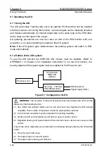
To use the ATA function the MRE-300 ATA module must be installed. (Refer to
APPENDIX 1 in Chapter 4 for installation instruction) To run the ATA function, the
bearing signal and the speed signal must be supplied to the Processor unit.
ATA module
MRE-300
(Option)
Gyro-log Interface
KSA-08A (Option)
Bearing signal
Speed signal (LOG)
Processor unit
Figure 6.7 Configuration of ATA
WARNING: The accuracy of the auto tracking function provided by the ATA could be
affected by the following factors:
(1) Sea clutter and weather clutter such as rain and snow may degrade the ATA tracking
capability. These clutter components should be appropriately reduced.
(2) Poor receiver sensitivity may also degrade the tracking capability.
(3) Faulty azimuth synchronization could be the cause of erratic vectors.
(4) Degraded bearing and speed data fed from external sensor devices also cause erratic
vectors.
If any of the errors stated above are detected, the following data provided by the ATA will be
erratic.
(1) The CPA and TCPA value.
(2) The target ship’s course and speed.
(3)
The target ship’s bearing and distance.
6-28
93142105-02

